This instruction show you guide on how to install variator rotating coupler for New Holland CX8080 combine.
| SERIES: | CX8000 series Tier IV – CX7000 Elevation series – CX8000 Elevation – CR Series Tier IV – CX Harvest Suite Ultra Cab – CX Harvest Suite™ Deluxe Cab – CR Harvest Suite Ultra Cab – TC Harvest Suite™ Comfort Cab |
| MODELS AFFECTED: | TC4.90,TC4080,TC5.70,TC5.80,TC5.90,TC5.90Hillside,TC5060,TC5070, TC5080 ,CX7.80 ,CX7.90 , CX8.70 , CX8.80 , CX8.85 , CX8.90 , CX7080 Elevation,CX7090 Elevation , CX8070 Elevation , CX8080 Elevation , CX8090 Elevation , CX8040 , CX8050 , CX8070 , CX8080 , CX8090 , CR10.90 , CR6.80 , CR6.90 , CR7.90 , CR8.80 , CR8.90 , CR9.80 , CR9.90 , CR6090 , CR7090 , CR8070 , CR8080 , CR8090 , CR9070 , CR9080 , CR9090 , CX5.80 , CX5.90 , CX5.90 Hillside , CX5.90 Laterale , CX6.80 , CX6.90 , CX6.90 Laterale |
Related Contents:
2024 CNH EST 9.10 9.2New Holland Diagnostic Software Free Download
The information in this Service Bulletin warns of the possibility that you may experience oil leakage from the rotating coupler on the:
Rotor variator of CR series Tier IV combines
Rotor variator of CR Harvest Suite Ultra Cab combines
Threshing drum variator of CX8000 series Tier IV combines
Threshing drum variator of CX Harvest Suite Ultra Cab combines
Feeder variator – If equipped
Chopper clutch variator on TC Combines
Main clutch variator on CX Midrange combines
You must be aware that a small amount of oil will always leak through the rotating coupler to provide lubrication to the components of the rotating coupler. An acceptable leak rate will cause small traces of oil in the dust around the rotating components. An excessive leak rate will cause continual drips of oil from the rotating coupler.
Only replace the rotating coupler if oil continuously drips from the rotating coupler during machine operation.
Oil that leaks from the rotating coupler can easily spread onto surrounding components.
To help minimize oil leaks from the rotating coupler, NEW HOLLAND introduced a new installation process for production assembly.
To help minimize oil leaks from the rotating coupler on customer machines, NEW HOLLAND advise you to follow the below installation procedures.
For flagship units, the new installation procedures are effective from the product identification number: xx1978xxx.
SERVICE
If you receive customer complaints of oil leaks from the rotating couplers, use the below instructions to avoid damage to the rotating coupler:
During the installation of the rotating coupler
During machine operation
Unit preparation
NOTE: The four reference points to the unit are the left-hand side, the right-hand side, the front of the unit, and the back of the unit. These reference points apply to someone that faces the direction of travel from a standing position that is behind the unit.
WARNING
Avoid injury!
Before you start any work on the unit, prepare the unit according to the following instructions.
Failure to comply could result in death or serious injury.
W1403B
Thoroughly clean the area on the unit that pertains to the service instructions for this Service Bulletin.
Park the unit on a hard, level surface.
Apply the parking brake.
Completely lower any attachments to the ground.
Relieve all of the hydraulic system pressure.
Shut down the engine.
Remove the ignition key.
Follow any specific instructions that pertain to the unit within the service instructions as necessary.
Service instruction
Below is the installation instruction for the rotating couplers:
84231982 for CR, and CX combines
86566566 for TC, CR, and CX combines.
CR Rotor Variator:
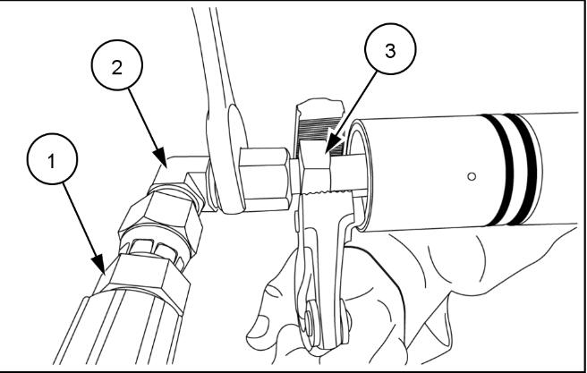
1.Install the flexible hose 84481797 (1) onto the 90° elbow union 86512933 (2).
2.Torque the flexible hose (1) to 15 N·m (11 lb ft) on the 90° elbow union.
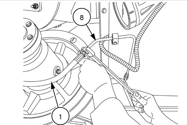
3.Install the hose (1) with the 90° elbow union (2) onto the rotating coupler (3).
4.Torque the 90° elbow union (2) to 15 N·m (11 lb ft) on the rotating coupler (3).
NOTE: To avoid damage to the rotating coupler during assembly, hold the rotating part of the coupler as figure 1 depicts.
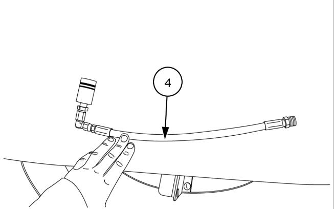
The assembly (4) is ready for installation.
5.Install the O-ring 86629585 (5) into the hub of the rotor-variator (6).
NOTE: Inspect the hub to ensure it is free of any dirt or damage before the installation of the O-ring.
NOTE: Soak the O-ring in clean oil prior to installation.
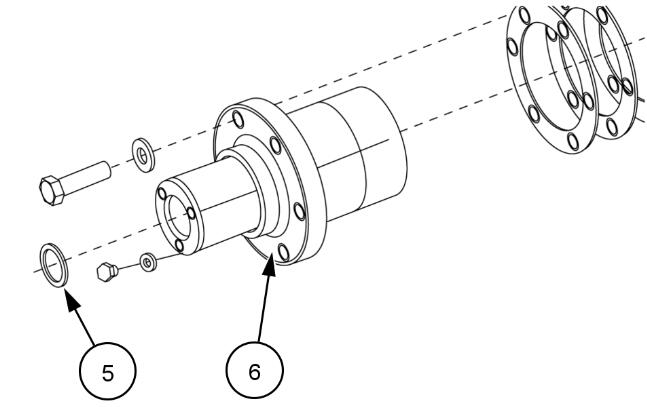
6.Carefully install the rotating coupler into the hub of the rotor-variator.
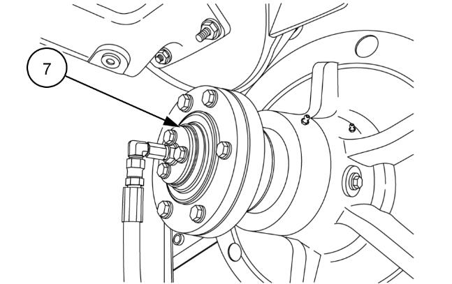
7.Install the retainer plate (7).
8.Torque the three bolts of the retainer plate to 15 – 20 N·m (11 – 15 lb ft).
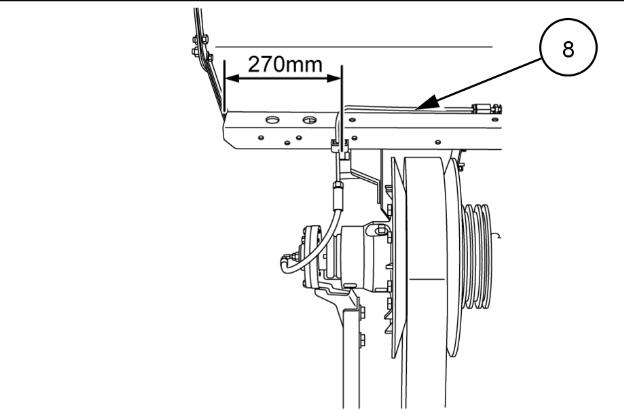
9.Make sure that the steel tube (8) is in the correct position.
NOTE: If the steel tube is not in the correct position it can cause a side-load on the rotating coupler. This side-load can result in the premature failure of the rotating coupling.
On CR combines with the wide frame, the bolt that secures the tube clamp must be in the hole which is 270 mm (10.6 in) from the end of the beam and 15 mm (0.6 in) from the rear of the beam, as figure 5 depicts.
Wide frame combines have 22 in rotors.
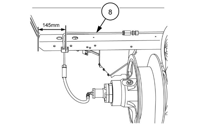
On CR combines with the narrow frame, the bolt that secures the tube clamp must be in the hole which is 145 mm (5.7 in) from the end of the beam and 15 mm (0.6 in) from the rear of the beam, as figure 6 depicts.
Narrow frame combines have 17 in rotors.
NOTE: For both the wide frame combines and the narrow frame combines, the tube clamp has the same orientation. See figures 5 and 6 .
If you need to move the steel tube (8), you must loosen the three tube clamps (9) to allow the steel tube to move from side to side.
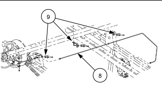
When the steel tube is in the correct position:
10.Connect the flexible hose (1) to the steel tube (8).
11.Torque the hose (1) to 15 N·m (11 lb ft).
NOTE: When you tighten the flexible hose onto the steel tube you must position the flexible hose carefully to relieve any torsional load on the flexible hose. You must then prevent rotation of the flexible hose as you tighten the clamp nut.
NOTE: Torsional load on the flexible hose can cause the premature failure of the rotating coupling.
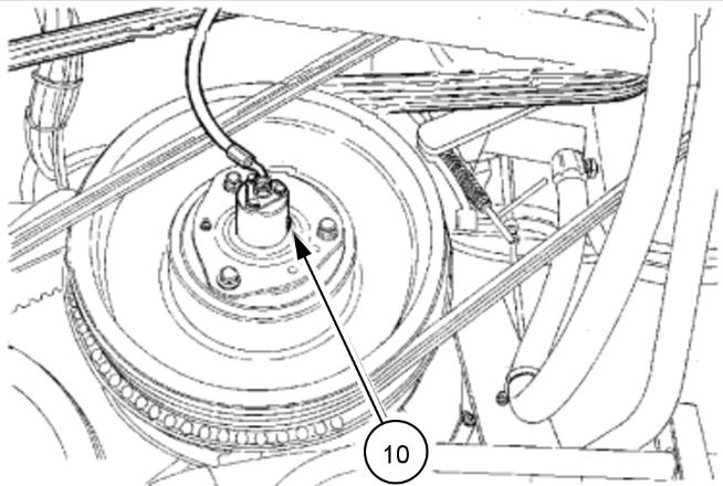
12.Use the variator-bleed screw (10) to purge all the air from rotor variator system.
CR Feeder Variator (If equipped):
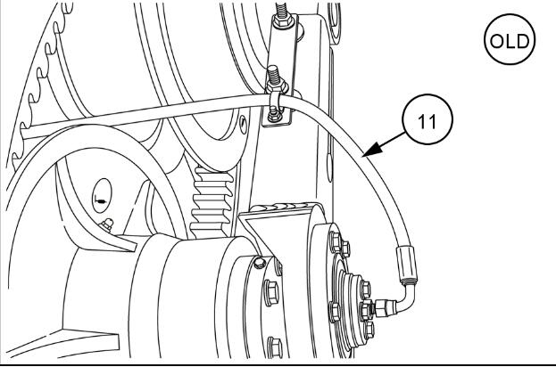
NOTE: For units prior to the build series xx1971xxx:
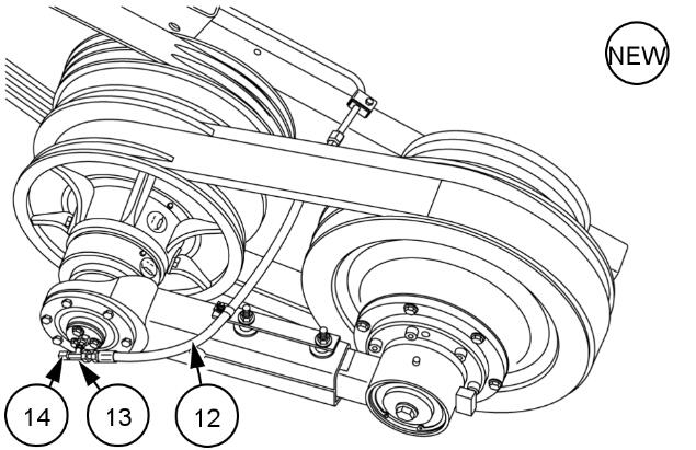
– Replace the existing flexible hose 47668512 (11) with the new hose 47846297 (12)
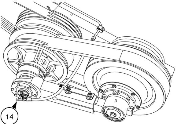
– There is an additional T-piece 86513012 (13) with the blanking cap 86511869 (14)
NOTE: The existing flexible hose 47668512 (11) was too short and could cause a side load on the rotating coupler. This side load can result in the premature failure of the rotating coupling.
The T-piece 86513012 (13) with the blanking cap 86511869 (14) provides a facility to bleed the air from the feeder-variator system.
The rotating coupler installation procedure for the feeder variator, is similar to the installation procedure to the rotor variator:
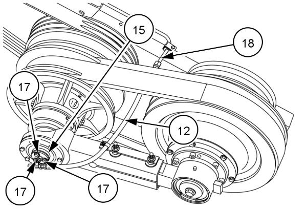
1.Install the blanking cap (14) onto the T-fitting (13) as Figure 11 depicts.
2.Install the flexible hose (12) onto the T-fitting (13) as Figure 11 depicts.
3.Torque the flexible hose (12) to 15 N·m (11 lb ft) on the T-fitting.
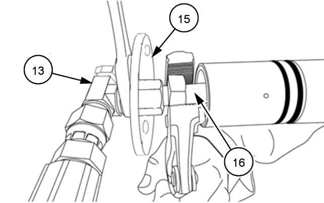
4.Place the retainer plate (15) over the T-fitting (13).
The rotating coupler installation procedure for the feeder variator, is similar to the installation procedure to the rotor variator:
5.Attach the T-fitting (13) onto the rotating coupler (16).
6.Torque the T-fitting (13)—fitting to 15 N·m (11 lb ft) on the rotating coupler (16).
NOTE: To avoid damage to the rotating coupler during assembly, hold the rotating part of the coupler as figure 12 depicts.
7.Install the O-ring 86629585 into the hub of the feeder-variator.
NOTE: Inspect the hub to ensure it is free of any dirt or damage before the installation of the O-ring.
NOTE: Soak the O-ring in clean oil prior to installation.
8.Carefully install the rotating coupler into the hub of the feeder variator.
9.Install the retainer plate (15).
10.Torque the three bolts (17) to 15 – 20 N·m (11 – 15 lb ft).
11.Attache the flexible hose (12) to the steel tube (18).
12.Torque the flexible hose (12) to 15 N·m (11 lb ft) on the steel tube (18).
NOTE: When you tighten the flexible hose onto the steel tube you must position the flexible hose carefully to relieve any torsional load on the flexible hose. You must then prevent rotation of the flexible hose as you tighten the clamp nut.
NOTE: Torsional load on the flexible hose can cause the premature failure of the rotating coupling.
Use the blanking cap (14) to purge all the air from feeder-variator system.
NOTE: The feeder variator does not contain a bleed screw. Follow the procedure to purge the air from the rotor variator, but, use the end cap (14) on the T-fitting instead of the bleed screw.
CX Drum Variator:
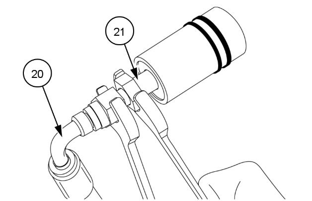
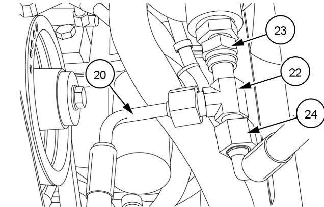
1.Place the retainer plate (19) over the flexible hose and then attach the hose (20) onto the rotating coupler (21).
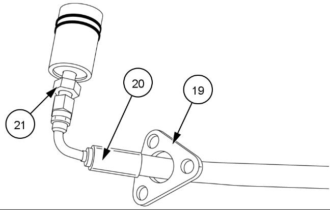
2.Torque the flexible hose (20) to 15 N·m (11 lb ft) on the rotating coupler (21).
NOTE: To avoid damage to the rotating coupler during assembly, hold the rotating part of the coupler as figure 16 depicts.
3.Carefully install the rotating coupler into the hub of the drum variator.
4.Install the retainer plate (19).
5.Torque the three bolts of the retainer plate to 15 – 20 N·m (11 – 15 lb ft).
6.Attach the other end of the flexible hose (20) to the T-fitting (22).
NOTE: To align the T-fitting with the flexible hose loosen the upper nut (23) of the T-fitting and the lower nut (24) of the T-fitting. After the alignment retighten the upper nut (23) of the T-fitting and the lower nut (24) of the T-fitting to 15 N·m (11 lb ft).
7.Torque the flexible hose (20) to 15 N·m (11 lb ft) on the T-fitting (22).
NOTE: When you tighten the flexible hose onto the steel tube you must position the flexible hose carefully to relieve any torsional load on the flexible hose. You must then prevent rotation of the flexible hose as you tighten the clamp nut.
NOTE: Torsional load on the flexible hose can cause the premature failure of the rotating coupling.
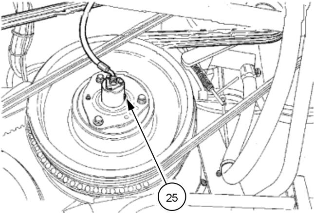
Use the variator-bleed screw (25) to purge all the air from drum variator system. See the Service Manual section: 66.321 – Variator belt – Install.
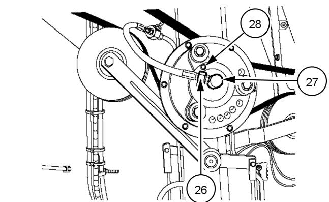
TC chopper clutch and CX midrange main clutch:
1.Remove the hydraulic hose (26) from the rotating connector (27) .
2.Plug the hydraulic connection to avoid oil leakage.
3.Remove rotating connector (27).
4.Apply LOCTITE® 242 onto the threads of the new rotating connector (27).
5.Tighten the rotating connector with a torque between 22.5 – 27.5 N·m (16.6 – 20.3 lb ft).
6.Reconnect the hydraulic hose (26) to the rotating connector (27).
7.Purge the air from the clutch by loosening the bleed bolt (28) and starting the engine. Engage the clutch until you see non aerated oil leaking out of the bleeding hole.
8.Tighten the bleeding bolt (28) with a torque between 7 – 11 N·m (5 – 8 lb ft).
9.Make sure there are no oil leaks.
More repair cases for New Holland machine,please refer to:New Holland Trouble Repair