Weeks ago,car-auto-repair.com share you a guide on how to disassemble engine for Doosan DL250-5.Here show a guide on how to assemble engine for Doosan DL250-5 excavator.
Related Contents:
Doosan Data Monitoring System DMS-5 DMS-3 Free Download
Daios Doosan EPC Excavator Part Catalog 2017 Download & Installation
Procedures:
Assemble the engine according to the following procedure:
1 Install the cylinder block.
- Place a wooden block or thick paper on the ground of the working area to prevent damage of the cylinderhead mounting surface. Then, set the head mounting surface toward the ground.
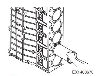
2 Install the cylinder liner.
- Stand the cylinder block with its flywheel side facing the ground.
- Clean the flange mounting surface and inside of the liner with compressed air thoroughly.
- After cleaning the cylinder liner, dry it completely and insert it into the cylinder block with hands.
- Apply engine oil to the inside of the cylinder liner.
3 Install the oil spray nozzle.
- Align the oil spray nozzle with the groove of the cylinder block using the oil spray nozzle installing jig.
- Install the relief valve.
- Tighten the mounting bolt to 20.6 N.m (2.1 kg.m,1 ft lb).
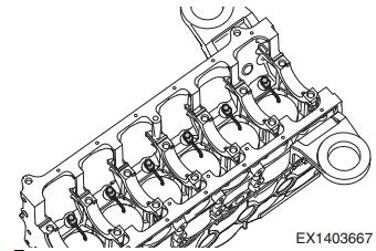
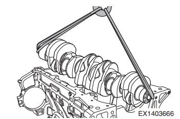
4 Install the crankshaft.
- Make sure to align the holes of the main bearing with the machined oil holes (2 ea) on the cylinder block during installation.
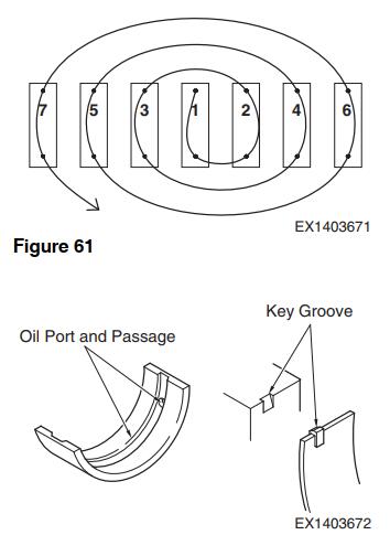
- Apply clean engine oil to the bearing surface.
- Heat the wear ring at 150°C for 10 minutes with a heater and install this front wear ring using an assembly jig.
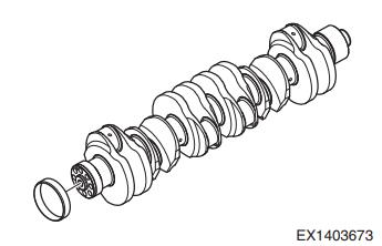
- Fit the bolts to both sides of the crankshaft temporarily. Then, place the crankshaft on the cylinder block using the mounting bolts.
- Apply engine oil to the pin and journal of the crankshaft.
- After oil application, install the thrust washer with it soil groove facing the outside.
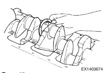
- Install the bearing and thrust washer to the bearing cap.
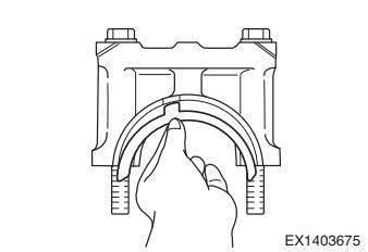
- Apply oil to the bearing and thrust washer.
- Install the bearing caps correctly by matching their numbers with the cylinder block numbers.
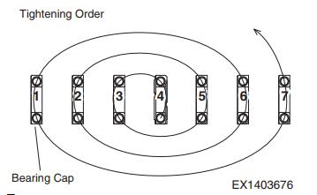
- Tighten the bearing cap bolts to the specified tightening torque in the specified order.
- Tighten both bolts evenly to set the bearing cap tight.
- Tighten the bolt according the following steps with a torque wrench:
– Step 1: Tighten the bolt to 49 N.m (5 kg.m,36.2 ft lb) until it is tightly set against the surface.
– Step 2: Tighten it to 147.1 N.m (15 kg.m,108.5 ft lb) with a torque wrench.
– Step 3: Tighten it to 245.1 N.m (25 kg.m,180.8 ft lb) with a torque wrench.
– Step 4: Tighten it to 294.1 N.m (30 kg.m,217 ft lb) with a torque wrench for the final time.
- Tighten the bearing caps in the following order:4 – 3 – 5 – 2 – 6 – 1 – 7.
- Rotate the installed crankshaft for 2 ~ 3 turns to check its free motion.
5 Install the tappet and camshaft.
- Cool a new bushing in dry ice for approximately 2hours.
- Press the new bushing into the cam bushing position of the cylinder block using a bench press.
- After pressing it in, measure the inside diameter of the cam bushing to check for its deformation.
- Apply engine oil to the face of the tappet and insert the tappet into its hole of the cylinder block.
- Apply engine oil to the camshaft hole and camshaft journal sections of the cylinder block.
- Insert the camshaft into its hole of the cylinder block.
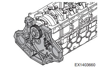
6 Install the timing gear case.
- Install the gasket to the cylinder block using a reference pin.
- Align the pin hole of the timing gear case with the reference pin.
- Install the timing gear case to the cylinder block.
- Set it tightly against the cylinder block by tapping its left and right with a urethane hammer.
- Tighten the relief valve to 25.5 N.m (2.6 kg.m,18.8 ft lb).
- Tighten the timing gear case mounting bolts to43.1 N.m (4.4 kg.m, 31.8 ft lb).
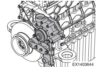
7 Install the fuel high-pressure pump.
- Install the gear of the fuel high-pressure pump using its jig.
- Tighten the gear nut to 107.9 N.m (11 kg.m, 79.6 ft lb).
- Tighten the mounting bolt to 43.1 N.m (4.4 kg.m, 31.8 ft lb).
- Install the fuel high-pressure pump to the timing gear case on the back of the flywheel housing.
- Tighten the flow screw to 29.4 N.m (3 kg.m, 21.7 ft lb).
- Tighten the nipple to 43.1 N.m (4.4 kg.m, 31.8 ft lb).
- Tighten the mounting bolts to the specified torque in the correct order.

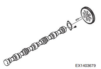
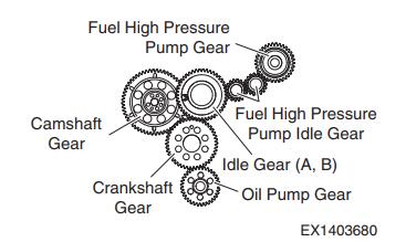
8Install the gear system.
- Install the thrust washer to the camshaft.
- Install the cam gear, aligning it with the pin hole of the camshaft.
- Tighten the camshaft thrust washer to 9.8 N.m(1 kg.m, 7.2 ft lb).
- Tighten the camshaft gear mounting bolt to 30.4 N.m(3.1 kg.m, 22.4 ft lb).
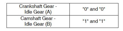
- Install the idle gear while aligning the marks on the crankshaft gear, camshaft gear and idle gear.
– Gear mark
F.Tighten the step idle gear to 60.8 N.m (6.2 kg.m, 44.8 ft lb).
- Tighten the fuel high-pressure pump idle gear to60.8 N.m (6.2 kg.m, 44.8 ft lb).
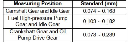
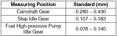
- Use a feeler gauge to check the backlash and end play of the gear.
– Backlash
– End play
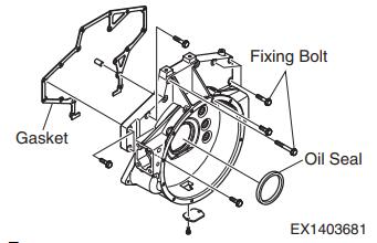
9 Install the flywheel housing.
- Install a guide bar to the cylinder block temporarily.
- Install the gasket to the cylinder block.
- Use a dowel pin and guide bar to install the fly wheel housing.
- Tighten the mounting bolts to 109.8 N.m (11.2 kg.m,81 ft lb) in the specified order.
- Remove the guide bar.
- Apply a thin film of engine oil to the outer surface of the oil seal and fit this seal into the flywheel housing.
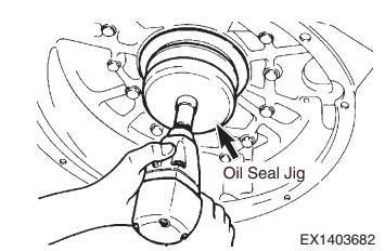
10 Install the rear oil seal.
- Align the oil seal with the crankshaft.
- Install the oil seal using its jig.
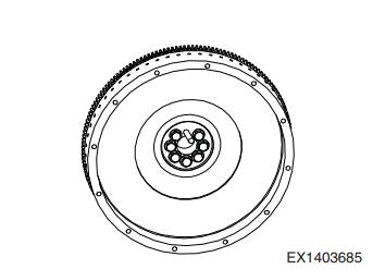
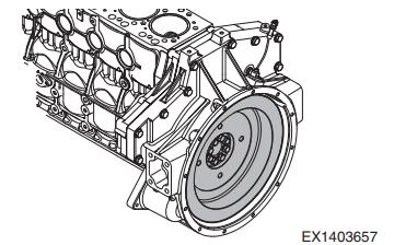
11Install the flywheel.
- Heat the ring gear with a gas burner evenly to expand
- Then, install it with a hammer.
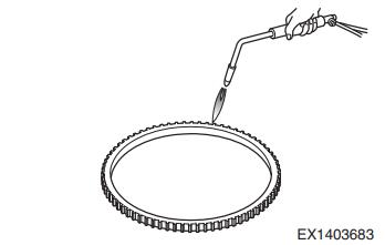
- The front of the wear ring can be identified by the mounting surface on the outer skirt.
- Fit a guide bar into the crankshaft bolt hole.
- Align the flywheel with the reference pin to install it temporarily.
- Apply adhesive (loctite #587) to the mounting bolt.
- Fit the bolts that have no guide pin in their holes.Then, remove the guide pin and fit the remaining bolt.
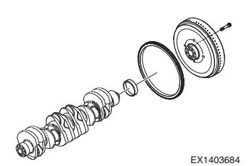
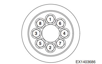
- Tighten the bolts (M14 x 1.5) to 196.1 N.m (20 kg.m,144.7 ft lb) in the specified order.
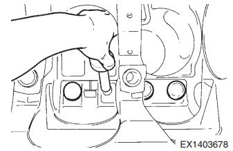
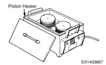
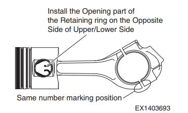
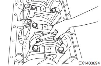
12 Install the piston and connecting rod.
- Heat the piston to approximately 100°C with a heater for 5 minutes.
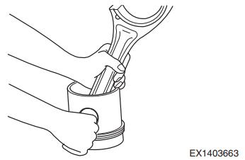
- When installing the piston and connecting rod, the weight controlling section at the small end of theconnecting rod and the oil gallery inlet (big hole side) of the piston should face the opposite direction.
- Apply oil to the pin hole of the piston and align this hole with the small end of the connecting rod. Then,tap the piston pin with a rubber hammer gently to install the connecting rod and piston.
- The openings of the snap rings should be set in the opposite direction (upwards and downwards).
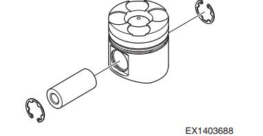
- Install the snap ring. Check its mounting condition.
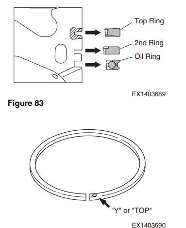
- Use piston ring pliers to install the piston ring to the piston.
- Make sure to install the piston ring in the correct direction. The mark “Y” or “TOP” on the ring connection should face up.
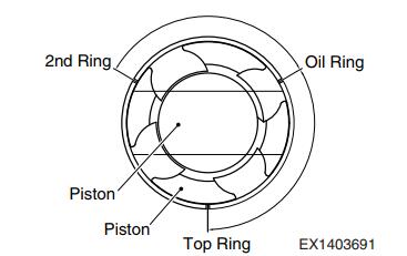
- Adjust each piston ring connection angle to 120° and fit a piston inserting jig into the piston.
- Install the connecting rod bearing while aligning it with the key groove. Then, apply oil to the bearing and piston.
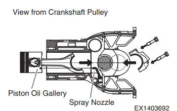
- Fit the piston so that the oil gallery inlet of the piston is in the same direction with the spray nozzle.
- Use a piston inserting tool to insert it into the cylinder liner. Be careful not to damage the ring by the tip of the liner.
- Fit the bearing to the connecting rod cap and apply oil on it.
- Check that the manufacturing serial numbers stamped on the connecting rod cap and connecting rod big end are the same.
- Install the connecting rod cap while aligning it with the reference pin.
- Apply oil to the mounting bolt and install the bolt loosely.
- Tighten the bolts to the specified tightening torque in the specified order using a torque wrench.
– Step 1: When tightening the connecting rod bolt, tighten it with a hand until its head touches the bolt seat of the connecting rod.
– Step 2: Tighten it to 39.2 ~ 58.8 N.m (4 ~ 6 kg.m, 28.9 ~ 43.4 ft lb) with a torque wrench.
– Step 3: Tighten it to 95.6 N.m (9.75 kg.m,70.5 ft lb) with a torque wrench for the final time.
- Shake the bearing cap with a hand. If it does not move, loosen and tighten it again.
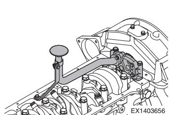
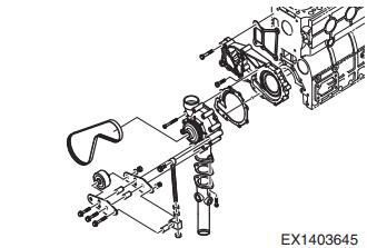
13 Install the oil pump and oil pipe.
- Install the reference pin to the bearing cap No. 7.
- Tap the oil pump with a urethane hammer gently to install it.
- Fit the washer and tighten the mounting bolt (M8) to21.6 N.m (2.2 kg.m, 15.9 ft lb). Tighten the bolt (M10) to 43.1 N.m (4.4 kg.m, 31.8 ft lb).
- Connect the oil feed pipe to the oil pump with the bolt.
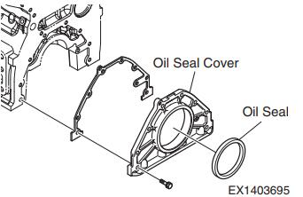
14 Install the front oil seal.
- Apply engine oil to the inside of the oil seal before installing the oil seal to the cover.
- Align a new oil seal with the center of the hole on the oil seal cover.
- Use an installing jig to install the oil seal.
- Tighten it to 21.6 N.m (2.2 kg.m, 15.9 ft lb).
15 Install the oil pan.
- Remove any protruded gasket on the timing gear case, cover, cylinder block and flywheel housing contact surface with a scraper thoroughly.
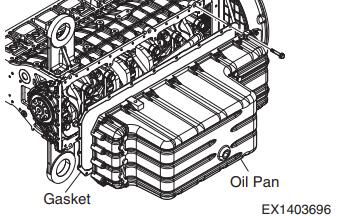
- Apply silicon on the surfaces where the used gasket was removed. Then, attach a new oil pan gasket.
- Install the oil pan.
- Tighten the bolts (4 ea) on both ends of the oil pan first and tighten the remaining bolts.
- Tighten the oil pan mounting bolt to 21.6 N.m(2.2 kg.m, 15.9 ft lb).
- Tighten the drain plug to 98.1 N.m (10 kg.m, 72.3 ft lb).
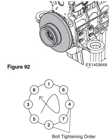
16 Install the crankshaft pulley and vibration damper.
- Install the vibration damper to the crankshaft pulley.
- Tighten the bolts in the correct order.
- Tighten the vibration damper to 60.8 N.m (6.2 kg.m,44.8 ft lb).
- Tighten the crankshaft pulley to 196.1 N.m (20 kg.m,144.7 ft lb).
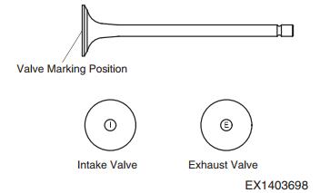
17 Install the intake and exhaust valves.
- Before installing the valve to the cylinder head, check the marks “I” and “E” on the valve head surface
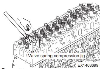
- Use a valve stem seal installing jig to install the valve stem seal to the valve guide.
- Install the valve cotter by pressing the retainer with a valve spring compressing tool after installing the valve spring and retainer.
- Tap the valve stem with a rubber hammer gently to check if the valve is corrected installed.
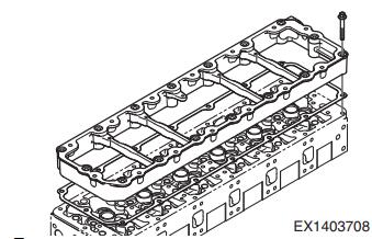
18 Install the cylinder head.
- Blow compressed air through the bolt hole of the cylinder head to remove any foreign materials.
- Clean the gasket mating surface of the cylinder head thoroughly.
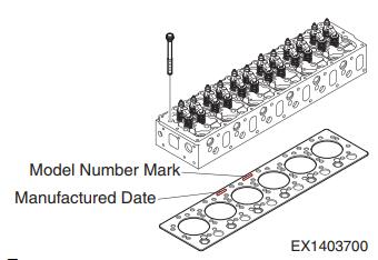
- Align the new gasket bolt hole with the reference pinon the cylinder block.
- When installing the gasket, its mark on the right should be upwards.
- Check if there is any foreign material in the combustion chamber.
- Install the cylinder head by aligning it with there taining pin.
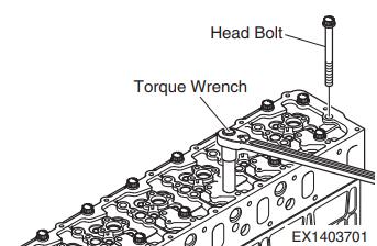
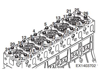
- Install the cylinder head bolt.
- Tighten the cylinder head bolts to the specified tightening torque in the specified order.
– Step 1: Tighten it for 1 to 2 threads with a hand, and then tighten it to 39.2 N.m (4 kg.m, 28.9 ft lb) temporarily.
– Step 2: Tighten it to 6 kg.m with a torque wrench.
– Step 3: Tighten it for 90° with a torque wrench.
– Step 4: Tighten it for 90° with a torque wrench.
– Step 5: Tighten it for 90° with a torque wrench for the final time.
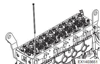
19 Install the push rod.
- Apply engine oil to the push rod.
- Insert the push rod into the push rod hole of the cylinder head.
20 Install the injector
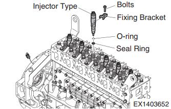
- Install the injector correctly according to the following steps.
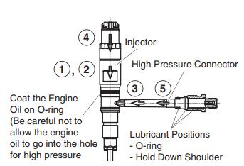
- Fit the O-ring to the injector and apply engine oil to the outer circumference surface.
- Align the seal ring with the injector hole on the cylinder head. Then, insert the injector gently.
- Align the injector mounting bolt with the thread of the head. Then, tighten the bolt for 2 ~ 3 threads with a hand.
- Set the injectors to the mounting positions of the injector mounting brackets (1 and 2) with the mounting bolts. Then, tighten them temporarily.
- After tightening the injectors temporarily, unscrew the bolts of the mounting brackets enough to move the injectors freely without load.
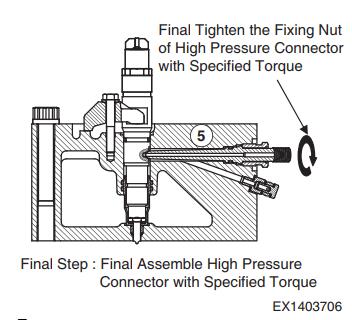
- Set the fuel high-pressure connector (3) with its balls set vertically.
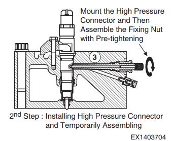
- Ensure that it is aligned with the groove in the hole on the side of the head on the intake manifold side.
- Align the fuel high-pressure connector through the hole on the side of the head, and push in the fuel high-pressure connector enough.
- Tighten the mounting nut (M22 x 15) of the fuel high pressure connector for 2 ~ 3 threads with a hand.
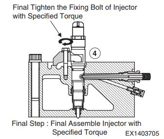
- Tighten the injector mounting bracket bolt to 2.9 N.m(0.3 kg.m, 2.2 ft lb) with a torque wrench.
- Tighten the injector mounting bracket bolt to14.7 + 4.9 N.m (1.5 + 0.5 kg.m, 10.8 + 3.6 ft lb) using a torque wrench.
- Tighten the injector mounting bracket mounting bolt (4)to 30.4 ~ 34.3 N.m (3.1 ~ 3.5 kg.m, 22.4 ~ 25.3 ft lb)
- Tighten the fuel high-pressure connector mounting nut(5) to 49 ~ 53.9 N.m (5 ~ 5.5 kg.m, 36.2 ~ 39.8 ft lb).
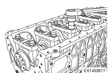
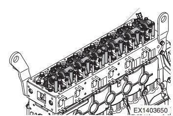
21 Install the rocker arm.
- For rocker arm assembly, install the spring, rocker arm, bracket, rocker arm, spring, washer and snap ring in order.
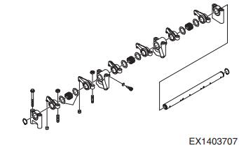
- Apply oil to the rocker arm bushing and shaft.
- Use the mounting bolts to install the rocker arm and bracket onto the cylinder head.
- Tighten the bolts to 36.8 N.m (3.75 kg.m, 27.1 ft lb)diagonally.
- Install the valve clearance adjusting screw to the rocker arm temporarily.
- Adjust the valve clearance.
22 Install the intermediate cover.
- Install a new gasket to the intermediate cover.
- Tighten the mounting bolt to 30.4 N.m (3.1 kg.m,22.4 ft lb).
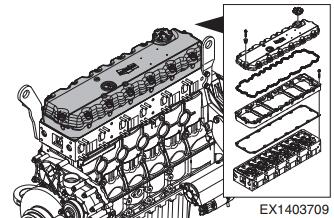
23 Install the cylinder head cover.
- Install a new rubber gasket to the cylinder head cover.
- Install the cylinder head cover to the cylinder head.
- Tighten the mounting bolt to 21.6 N.m (2.2 kg.m,15.9 ft lb).
- Install the oil filler cap to the cylinder head cover.
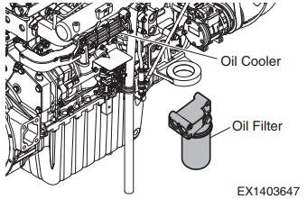
24 Install the oil cooler.
- Install the oil cooler and gasket to the cylinder block.
- Tighten the bolt to 21.6 N.m (2.2 kg.m, 15.9 ft lb).
25 Install the oil filter.
- Install the oil filter cartridge using a special service tool.
26 Install the coolant pump.
- Install the coolant pump cover and coolant pump gasket.
- Install the coolant pump to the cylinder block.
- Tighten the mounting bolt to 21.6 N.m (2.2 kg.m,15.9 ft lb).
- Install the idle pulley bracket.
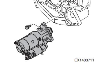
- Install the start motor.
- Install the start motor to the stud bolt of the fly wheel housing.
- Tighten the mounting nut to 78.5 N.m (8 kg.m,57.9 ft lb).
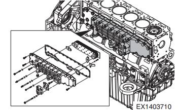
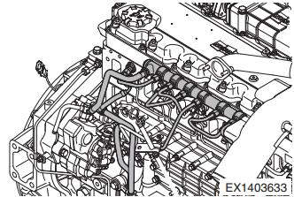
28 Install the common rail and high-pressure pipe.
- Install the common rail to the cylinder block.
- Connect the fuel feed pipe between the common rail and fuel high-pressure connector.
- Tighten the fuel high-pressure pipe on the common rail side to 24.5 N.m (2.5 kg.m, 18.1 ft lb).
- Tighten the fuel high-pressure pipe on the fuel high pressure connector side to 27.5 N.m (2.8 kg.m,20.3 ft lb).
- Tighten the common rail fuel high-pressure pipe from the fuel high-pressure pump to 20.6 N.m (2.1 kg.m,15.2 ft lb).
- Tighten the common rail mounting bolt to 21.6 N.m(2.2 kg.m, 15.9 ft lb).
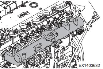
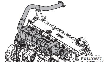
29 Install the intake manifold.
- Install a new gasket between the cylinder head and intake manifold.
- Tighten the mounting bolt to 43.1 N.m (4.4 kg.m,31.8 ft lb).
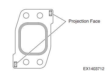
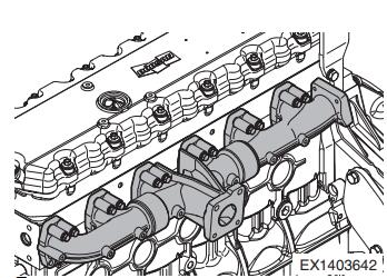
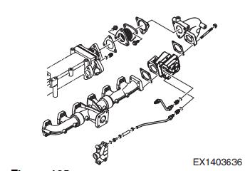
30 Install the exhaust manifold.
- Install the exhaust manifold gasket to the stud bolt of the cylinder head.
- \Align the gas outlet of the cylinder head with the gasket hole.
- Install the exhaust manifold.
- Tighten the mounting bolt to 49 N.m (5 kg.m,36.2 ft lb).
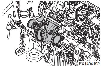
31 Install the turbocharger.
Install a new gasket to the stud bolt of the exhaust manifold.
Install the turbocharger.
Connect the oil feed pipe and drain pipe.
Tighten the clamp for the rubber hose to connect the air pipe and turbocharger.
Tighten the mounting bolt to 78.5 N.m (8 kg.m,57.9 ft lb).
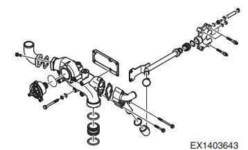
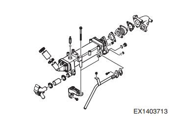
32 Install the coolant pipe and thermostat.
Install the gasket to the cylinder head.
Install the housing to the thermostat.
Install the O-ring to the thermostat.
Connect the coolant pipe.
Tighten the bolt to 21.6 N.m (2.2 kg.m, 15.9 ft lb).
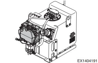
33 Install dosing module.
Install the dosing module to the UREA tank with the mounting bolts.
Install the cover for the dosing module with the mounting bolts.
Connect the dosing pipe.
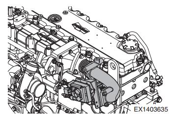
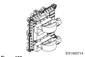
34 Install the EGR cooler.
- Install the EGR cooler mounting bracket to the cylinder head with the mounting bolts.
- Install the EGR cooler to the bracket with the mounting bolts.
- Connect the pipe and hose to the EGR cooler.
35 Install the EGR valve.
- Install the exhaust pipe to the EGR cooler with the gasket and secure it with the mounting bolt.
- Install the EGR valve to the exhaust pipe with the gasket and secure it with the mounting bolt.
36 Install the ECU (Electrical Control Unit).
- Fix the ECU mounting plate.
- Install the ECU.
37 Install the crankshaft speed sensor and camshaft speed sensor.
Measure the clearance between the mountin gsection of the crankshaft speed sensor and flywheel.
Use shims to adjust this clearance to 1.0 mm.
Tighten the crankshaft speed sensor to 9.8 N.m(1 kg.m, 7.2 ft lb).
Measure the clearance between the mounting section of the camshaft speed sensor and timing gear. Use shims to adjust this clearance to 1.0 mm.
Tighten the camshaft speed sensor to 9.8 N.m(1 kg.m, 7.2 ft lb).
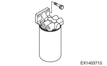
38 Install the fuel filter.
- Fuel needs to flow through the following componentsin this order: fuel feed pump, fuel filter, fuel high pressure pump and common rail. Connect the fuelfeed pipe correctly according to the arrow direction mark on the head of the fuel filter to ensure correct fuel flow.
- Tighten the fuel pipe to 29.4 N.m (3 kg.m, 21.7 ft lb).
- Tighten the fuel temperature sensor to 21.6 N.m(2.2 kg.m, 15.9 ft lb).
- Tighten the mounting bracket to 43.1 N.m (4.4 kg.m,31.8 ft lb).
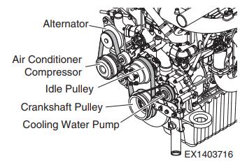
39 Install the alternator and belt.
- Install the alternator and A/C bracket. Then, secure them with the mounting bolts.
- Install the alternator, A/C compressor and idle pulley.
- Tighten the alternator mounting bolt to 75.5 N.m(7.7 kg.m, 55.7 ft lb).
- Tighten the alternator support mounting bolt to49 N.m (5 kg.m, 36.2 ft lb).
- Install the belt and adjust its tension with its adjusting bolt.
40 Connect the air pipe and install the air heater.
- Install the air pipe, air heater and throttle valve.
- Tighten the mounting bolt to 21.6 N.m (2.2 kg.m,15.9 ft lb).
41 Fit the dipstick.
- Apply adhesive (loctite #262) to the guide tube.
- Install the guide tube and dipstick to the oil pan.
42 Connect the cables and harnesses of the engine to each sensor.
43 Mount the engine to the machine.
44 Add engine oil.
- Open the oil filler cap on top of the cylinder head cover and add engine oil to it.
45 Add coolant.
- Open the radiator cap and add coolant.
More topics for Doosan,please refer to:Doosan Trouble Repair