This instruction show you guide on how to remove and install engine for New Holland LW130.B wheel loader.
Related Contents:
2024 CNH EST 9.10 9.2New Holland Diagnostic Software Free Download
New Holland Agricultural & Construction Parts+Service Manual Free Download
Procedures:
STEP 1
Park machine on a level surface and lower bucket to floor. Stop engine. Actuate brake pedal several times to discharge brake accumulators. Move loader control lever back and forth at least 30 times to release any pressure from hydraulic circuit.
STEP 2
Put articulation lock in LOCKED position.
STEP 3
Slowly loosen the filler cap for hydraulic reservoir to release air pressure in hydraulic reservoir.
STEP 4
Put master disconnect switch in OFF position.
STEP 5
Disconnect battery cable from LH battery negative post. Put a plastic cap over the negative post.
STEP 6
Disconnect battery cable from RH battery positive post. Put a plastic cap over the positive post.
STEP 7
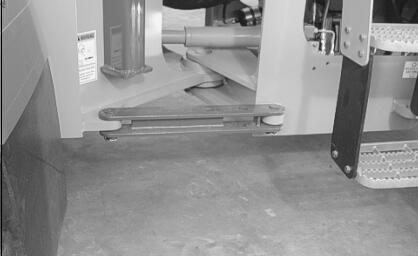
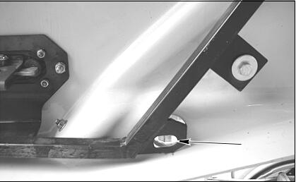
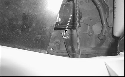
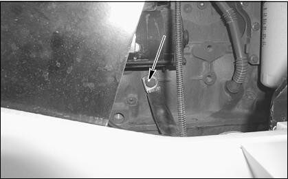
Open the engine compartment side panel, attach a lifting eye to the hole in the lower portion of the panel.
STEP 8
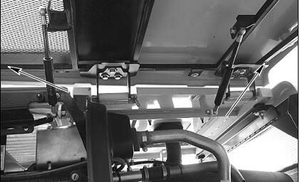
Attach lifting straps to the hinge side of the hood,attach suitable lifting equipment to the straps and take up slack in the straps.
STEP 9
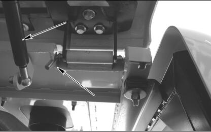
Disconnect the gas cylinders from the side panel and hood. Remove hinge pins, remove panel from
machine.
STEP 10
Repeat steps 7 through 9 for the other side panel.
STEP 11
Attach lifting straps to the center hood section.
STEP 12
Connect lifting equipment to the lifting straps. Take up all slack in strap connected to hood.
STEP 13
Remove two nuts and bolts and four washers securing the rear of the hood.
STEP 14

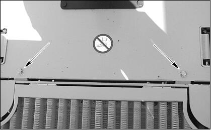
Remove the two front bolts and washers securing the front of the hood.
STEP 15
Carefully raise and remove hood from loader. Lower hood onto suitable platform and disconnect lifting equipment.
STEP 16
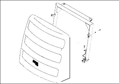
Remove the four rear grill mounting bolts, remove the grill. Remove the six rear grill frame mounting bolts and nuts, remove the frame.
STEP 17
Tag and disconnect engine wiring harness connector from air filter restriction switch.
STEP 18
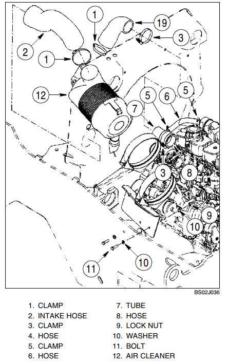
Loosen clamp (1) on air cleaner intake hose (2) and remove intake hose.
STEP 19
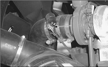
Loosen clamps (3 and 5) on crankcase hose (6) and turbocharger intake hose (8). Disconnect hose (6) from breather pipe. Disconnect hose (8) with tube (7) attached from turbocharger.
STEP 20
Support air cleaner assembly (12) and remove two lock nuts (9), bolts (11), four washers (10). Remove air cleaner (12) and associated parts as an assembly.
STEP 21
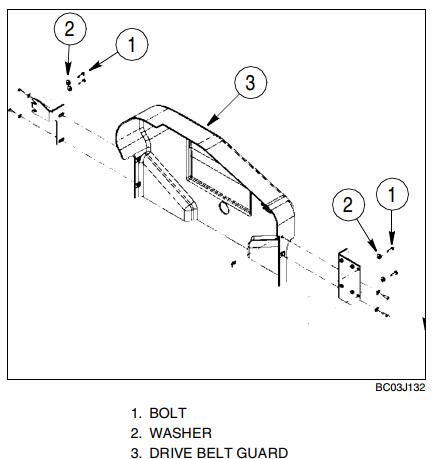
Remove four bolts (1) and washers (2) securing drive belt guard (3) to the frame.
STEP 22
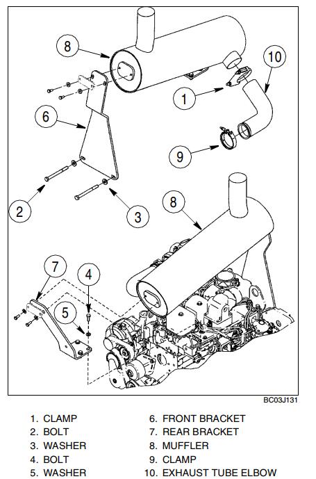
Remove clamp (1) securing exhaust tube elbow (10) to muffler (8).
STEP 23
At front of engine, remove two bolts (2) and washers (3) securing muffler front mounting bracket (6).
STEP 24
Support muffler (8) and brackets (6 and 7) and remove two bolts (4) and washers (5) at rear of engine. Remove muffler and brackets as an assembly from engine.
STEP 25
Loosen clamp (9) and remove exhaust tube elbow (10) from turbocharger.
STEP 26
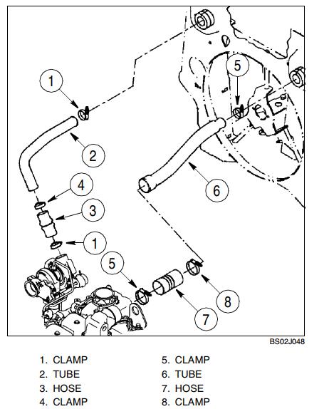
Loosen two clamps (1). Remove tube (2) and hose (3) as an assembly.
STEP 27
Loosen two clamps (5). Remove tube (6) and hose (7) as an assembly.
STEP 28
Disconnect grounding strap from left side of engine.
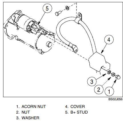
STEP 29
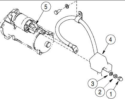
Remove acorn nut (1), nut (2), and washer (3) securing cover (4) to starter. Remove cover.
STEP 30
Remove nut and washer securing cables to starter B+ stud (5). Identify, tag, and disconnect both cables.
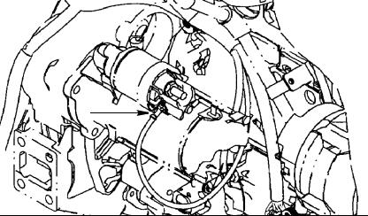
STEP 31
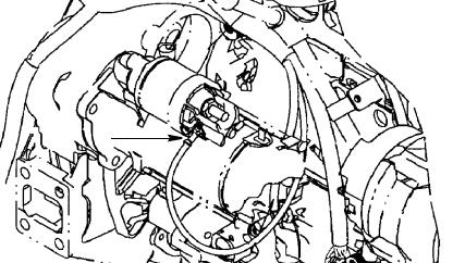
Identify and tag rear chassis harness wire connected to starter solenoid terminal. Disconnect rear chassis harness wire from terminal.
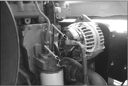
STEP 32

Identify, tag, and disconnect engine harness from alternator.
STEP 33
Identify, tag, and disconnect connector from engine coolant temperature sender. Remove bolt and
washer securing cable clamp to engine.
STEP 34
If wheel loader is equipped with air conditioning,identify, tag, and disconnect connector from air
conditioner compressor clutch. Identify. tag, and disconnect connector from air conditioning high
pressure switch.
STEP 35
Support air conditioning compressor and remove bolts securing compressor. Remove compressor and place on battery cover.
STEP 36
Remove bolts and bracket securing fuel line to rear of engine.
STEP 37
Remove bolts, nuts and clamps securing wiring harness to rear of engine.
STEP 38
If equipped, identify, tag, and disconnect wire from grid heater.
STEP 39
If equipped, identify, tag, and disconnect connector from fuel filter heater.
STEP 40
If equipped, identify, tag, and disconnect connector
from fuel filter temperature switch.
STEP 41
Disconnect injection pump fuel solenoid and oil pressure sending unit.
STEP 42
STEP 43
Connect a vacuum pump to hydraulic reservoir. If a vacuum pump is not available, drain the hydraulic oil (hydraulic reservoir holds 68.5 liters (18 gallons) of oil). Turn on vacuum pump (if available). Tag,disconnect, and plug hoses connected to brake pump. Plug hoses securely and cap fittings. Turn off vacuum pump.
STEP 44

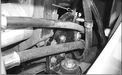
Remove bracket mounting hydraulic brake pump lines and fuel line from bell housing.
STEP 45
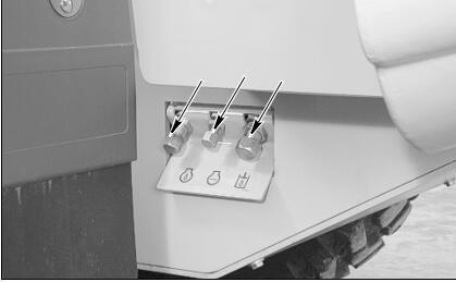
Put a 37.8 liter (10 gallon) container below radiator drain. Remove cap and drain coolant into container.Install cap after coolant has drained.
STEP 46
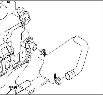
Loosen two clamps. Disconnect and remove bottom hose.
STEP 47
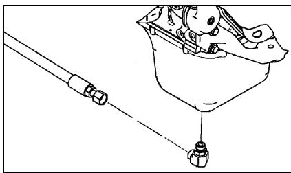
Loosen two clamps (1) securing bleed line hose (2).
Disconnect bleed line hose (2) from fittings.
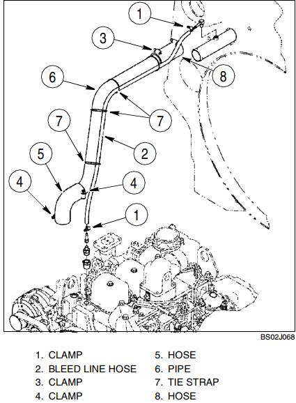
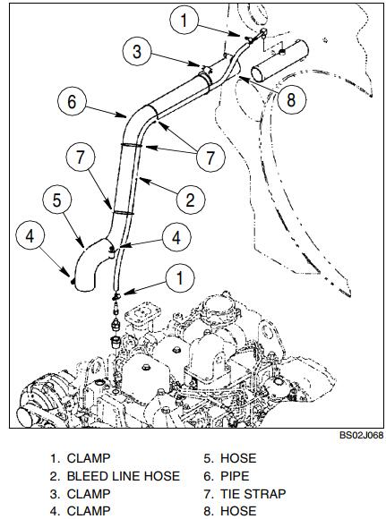
STEP 48
Loosen clamps (3 and 4). Disconnect and remove hose (5) from engine and pipe (6). Disconnect and remove pipe (6) with bleed line hose (2) attached from hose (8). If necessary, cut, remove, and discard tie straps (7) to separate bleed line hose (2) from pipe (6).
STEP 49

Put a 18.9 liter (5 gallon) container below engine oil drain. Remove cap and drain engine oil into
container. Install cap after oil has drained.
STEP 50
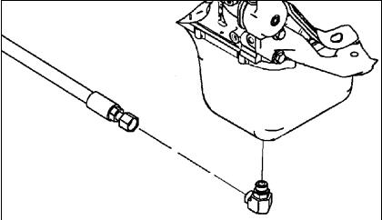
Disconnect hose from elbow installed in engine oil pan. Put a plug in hose and a cap on fitting.
STEP 51
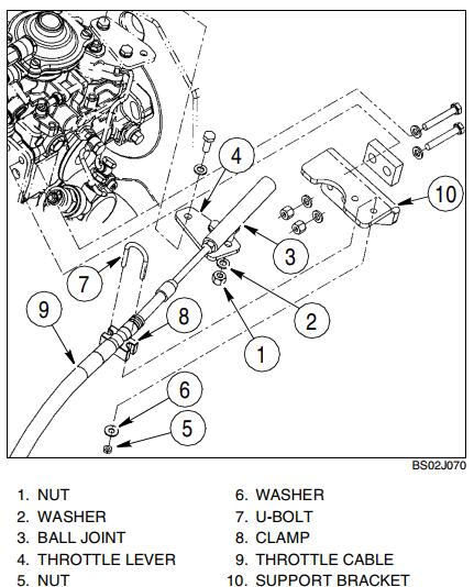
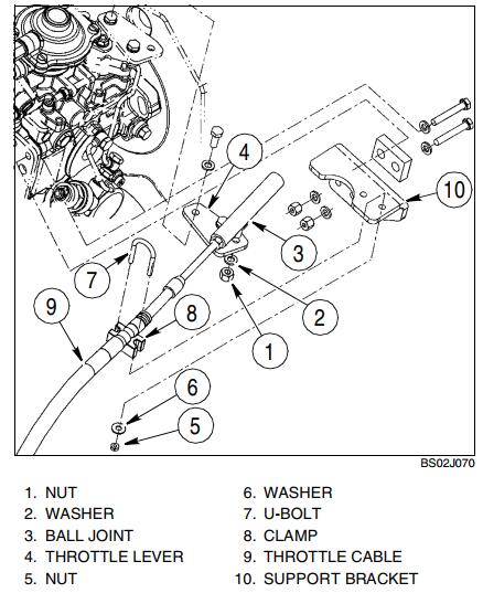
Remove nut (1) and washer (2) securing ball joint (3) to throttle lever (4).
STEP 52
Remove two nuts (5) and washers (6), U-bolt (7), and clamp (8) securing throttle cable (9) to support bracket (10). Position throttle cable away from engine.
STEP 53
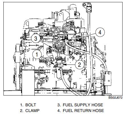
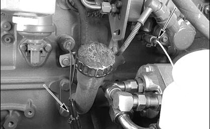
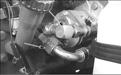
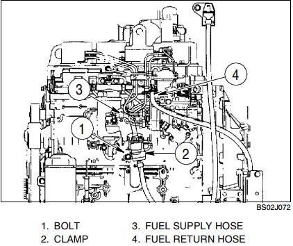
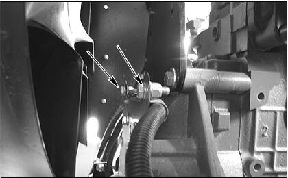
Remove bolt (1) and washer securing clamp (2) holding in-line fuel filter to engine block. Tag and
disconnect fuel supply hose (3) from priming pump.Plug hose and cap fitting. Tag and disconnect fuel return hose (4) from fuel injection pump. Plug hose and cap fitting.
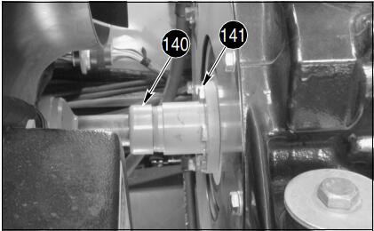
STEP 54
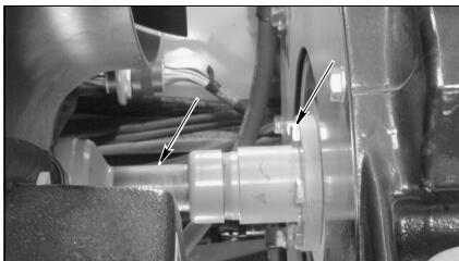
At front of engine, remove six bolts securing drive shaft to engine coupling. Use a pry bar to move drive shaft away from engine coupling.
STEP 55
Connect lifting equipment to engine lifting brackets.
Take up all slack in lifting equipment.
STEP 56
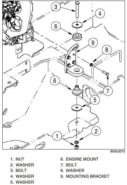
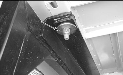
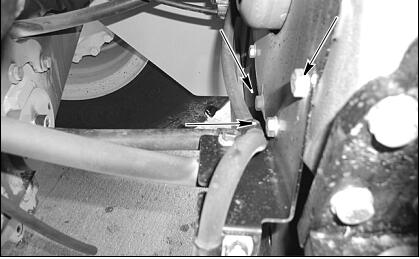
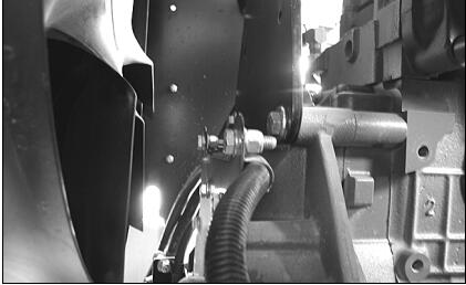
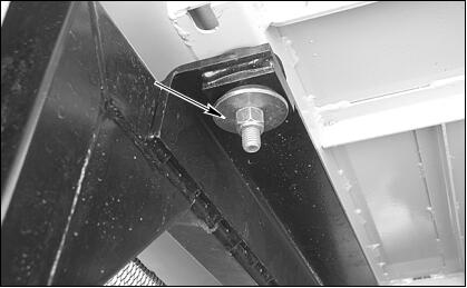
Remove nut (1), washer (2), bolt (3), and washer (4) securing engine and mounting brackets to chassis.
STEP 57
Slowly raise engine from rear chassis. Check and be sure all harness connections, hoses, and throttle cable have been disconnected and are positioned out of the way. Remove engine from machine.
Installation
STEP 58
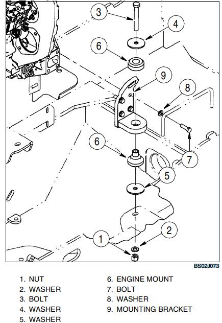
If engine mounting brackets (9) were removed,position bracket on engine and secure using bolts (7) and washers (8). Torque bolts to 118 to 130 Nm (87 to 98 lb-ft). If necessary, install new engine mount (6) in mounting bracket. Repeat this step to install remaining engine mounting brackets and engine mounts as necessary.
STEP 59
Connect suitable lifting equipment to engine lifting brackets. Slowly raise engine and move into position over rear chassis. Be sure all harness connections and hoses are out of the way then lower engine. Put washer (5) between front engine mount (6) and chassis. Install washers (4 and 5), bolt (3), washer (2), and nut (1) in engine front mounts. Lower engine into position.
STEP 60
Torque bolts (3) to a torque of 244 to 298 Nm (180 to 220 lb-ft).
STEP 61
Disconnect lifting equipment from engine lifting brackets.
STEP 62
At front of engine, position drive shaft on engine coupling. Put Loctite 242 on threads of six bolts.
Install six bolts and tighten to a torque of 53 to 62 Nm (39 to 46 lb-ft).
STEP 63
Install bracket mounting hydraulic brake pump lines and fuel line to bell housing.
STEP 64
Turn on vacuum pump connected to hydraulic reservoir. Remove caps from brake pump fittings and plugs from brake pump hoses. Connect hoses to brake pump following tags installed during removal.Remove and discard tags. Turn off and disconnect vacuum pump from hydraulic reservoir.
STEP 65
Remove plug from fuel return hose (4) and cap from fuel injection pump fitting. Connect fuel return hose to fuel injection pump. Remove plug from fuel supply hose (3) and cap from priming pump fitting. Connect fuel supply hose to priming pump. Position clamp (2) holding in-line fuel filter and secure to engine block using washer and bolt (1).
STEP 66
Route throttle cable (9) up and over towards fuel injection pump. Put clamp (8), throttle cable (9), and U-bolt (7) on support bracket (10) and secure using two washers (6) and nuts (5).
STEP 67
Install ball joint (3) on throttle lever (4) and secure using washer (2) and nut (1).
STEP 68
Remove plug from oil drain hose and cap from fitting installed in engine oil pan. Connect hose to fitting and tighten.
STEP 69
Put clamp (3) on hose (8). Connect pipe (6) to hose (8). Position clamp (3) and tighten to a torque of 10.1 to 11.3 Nm (90 to 100 lb-inch). Put clamps (4) on hose (5). Connect hose (5) to pipe (6) and engine coolant outlet. Position clamps (4) and tighten to a torque of 10.1 to 11.3 Nm (90 to 100 lb-inch).
STEP 70
Put hose clamps (1) on bleed line hose (2) and connect hose to fittings. Position clamps (1) and
tighten to a torque of 10.1 to 11.3 Nm (90 to 100 lb-inch). Install three tie straps (7) to secure bleed
line hose (2) to pipe (6).
STEP 71
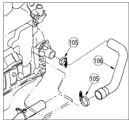
Put clamps on hose. Connect hose between bottom pipe and engine coolant inlet. Position clamps and tighten to a torque of 10.1 to 11.3 Nm (90 to 100 lb-inch).
STEP 72
If equipped, position and support air conditioning compressor on mounting bracket. Secure using bolts washers.
STEP 73
If wheel loader is equipped with air conditioning,connect connector to air conditioning compressor
clutch following tag installed during removal. Connect connector to air conditioning high pressure switch following tag installed during removal. Remove and discard tags.
STEP 74
Install drive belt, take up slack in drive belt and tighten bolts.
STEP 75

Connect injection pump fuel solenoid and oil pressure sending unit.
STEP 76
If equipped, connect connector to fuel filter temperature switch following tag installed during
removal. Remove and discard tag.
STEP 77
If equipped, connect connector to fuel filter heater following tag installed during removal. Remove and discard tag.
STEP 78
If equipped, connect wire to grid heater following tag installed during removal. Remove and discard tag.
STEP 79
Connect connector to engine coolant temperature sender following tag installed during removal.
Remove and discard tag.
STEP 80
Position clamp holding engine harness on flywheel housing cover.
STEP 81
Connect wires to alternator.
STEP 82
Connect harness wire to starter solenoid terminal following tag installed during removal. Remove and discard tag.
STEP 83
Connect cables to starter B+ stud (5) following tags installed during removal. Install nut and washer to secure cables. Remove and discard tags from cables.
STEP 84
Put cover (4) on starter. Install washer (3), nut (2),
and acorn nut (1) to secure cover (4).
STEP 85
Connect grounding strap from left side of engine.
STEP 86
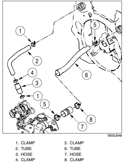
Install tube (6) and hose (7) as an assembly. Tighten two clamps (5) to a torque of 10.1 to 11.3 Nm (90 to 100 lbs-inch).
STEP 87
Install tube (2) and hose (3) as an assembly. Tighten two clamps (1) to a torque of 10.1 to 11.3 Nm (90 to 100 lbs-inch).
STEP 88
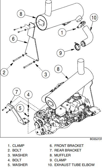
Put clamp (9) on exhaust tube elbow (10). Install exhaust tube elbow and clamp on turbocharger. Do not tighten clamp at this time.
STEP 89
Install and support muffler (8) and brackets (6 and 7) on engine while connecting muffler to exhaust tube elbow (10). Install two washers (5) and bolts (4) finger tight.
STEP 90
At front of engine, install two washers (3) and bolts (2) to secure muffler front mounting bracket (6).Tighten bolts (2) to a torque of 118 to 133 Nm (87 to 98 lb-ft). Tighten bolts (4) to a torque of 68 to 77 Nm (50 to 56 lb-ft).
STEP 91
Install clamp (1). Tighten clamp (1) to a torque of 20 to 25 Nm (15 to 18 lb-ft). Tighten clamp (9) to a torque of 4.8 to 5.2 Nm (42.5 to 46 lb-ft).
STEP 92
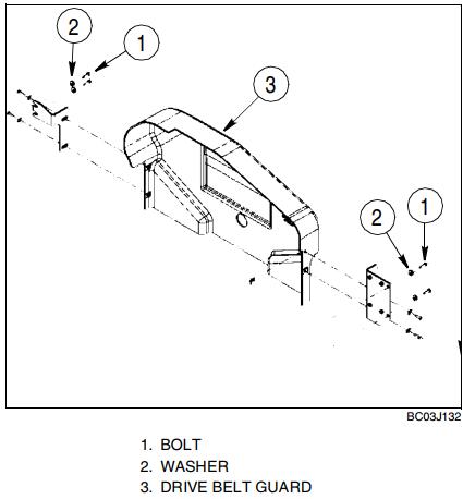
Position drive belt guard (3) and secure using four washers (2) and bolts (1) to the frame.
STEP 93
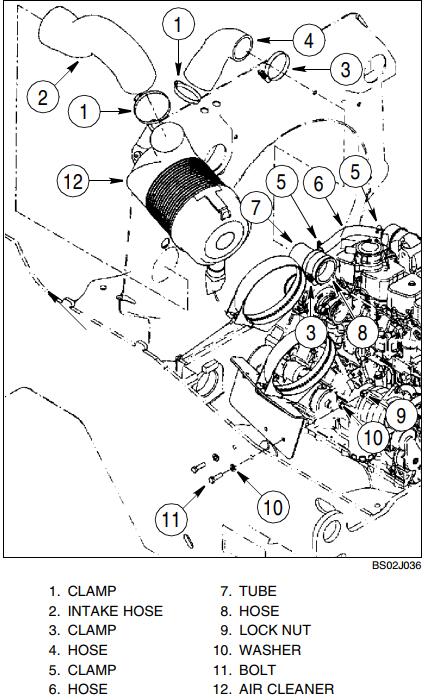
Position air cleaner assembly (12) and support as an assembly. Secure using two washers (10), bolts (11) and lock nuts (9).
STEP 94
Connect turbocharger intake hose (8) attached to tube (7) to turbocharger and crankcase hose (6) to breather pipe. Position clamps (3 and 5) and tighten.
Tighten clamps (3) to a torque of 10.1 to 11.3 Nm (90 to 100 lb-inch).
STEP 95
Connect air cleaner intake hose (2) between cooling frame and air cleaner inlet. Position clamp (1) and tighten to a torque of 3.6 to 4.5 Nm (32.4 to 39.6 lb-inch).
STEP 96
Remove plastic cap installed over the positive post during removal. Connect battery cable to RH battery positive post.
STEP 97
Remove plastic cap installed over the negative post during removal. Connect battery cable to LH battery negative post.
STEP 98

Connect engine wiring harness connector to air filter restriction switch following tag installed during removal. Remove and discard tag.
STEP 99
Install the frame and secure with six mounting bolts and nuts. Install the grill and secure with four
mounting bolts.
STEP 100
Carefully raise and position hood onto loader.
STEP 101
Install the two front bolts and washers securing the front of the hood.
STEP 102

Install two nuts and bolts and four washers securing the rear of the hood.
STEP 103
Place engine compartment side panel into position.
STEP 104
Install hinge pins, connect the gas cylinders to the side panel and hood.
STEP 105
Repeat steps 103 and 104 for the other side panel.
STEP 106
BD00M031
Check and make sure that drain caps are tight.
STEP 107
Install a new oil filter on engine. Fill engine with 10.5 liters (11 quarts) of New Holland AMBRA engine oil (SAE 15W-40).
STEP 108
If hydraulic reservoir was drained, fill reservoir with 68.5 liters (18 gallons) of New Holland AMBRA
Hydrosystem 46 fluid.
STEP 109
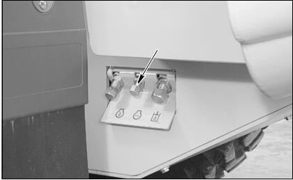
Fill engine coolant system with a solution of 50% Ethylene Glycol and 50% water. Cooling system
capacity is 34.1 liters (9 gallons). Install the radiator cap. Fill the coolant reservoir up to the FULL mark on the reservoir.
STEP 110
Put master disconnect switch in ON position.
WARNING: Hot coolant can spray out if radiator cap is removed. To remove radiator cap: Let system cool, turn to first notch, then wait until all pressure is released. Scalding can result from fast removal of radiator cap.
STEP 111
Start engine and run the engine at low idle. Run the engine at operating temperature for approximately five minutes to completely mix the Ethylene Glycol and water. When the coolant is at operating temperature, stop the engine. When engine has cooled, check the coolant level at the reservoir.
STEP 112
Lower and close hood side panels.
STEP 113
Put articulation lock in OPERATING position.
More topics for New Holland repair,pls refer to:New Holland Trouble Repair