This document show you guide on how to remove and install engine and work equipment pump assembly.For more Komatsu case,please refer to:Komatsu trouble repair.
Preparations:
Komatsu CSS Full Set 2018 2014 Parts Viwer Free Download
Remove and Install Front Oil Seal for Komatsu PC130-8 Excavator
Procedures:
Removal
Stop the machine on a level ground, lower the work equipment to the ground, stop the engine, and set the lock lever in the lock position.
Disconnect the cable from the negative (–) terminal of the battery.
Loosen the hydraulic tank cap gradually to release the pressure in the hydraulic tank.
Put tags to the pipings to prevent a mistake in re-connecting them.
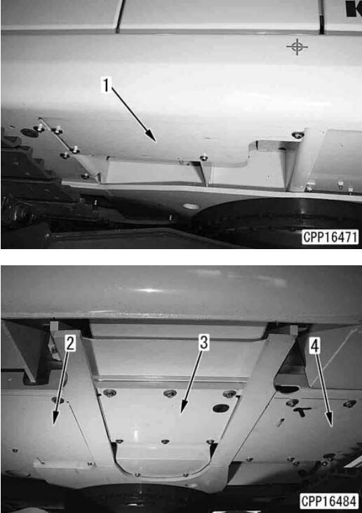
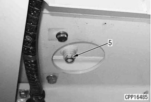
1.Remove hydraulic tank undercover (1), radiator undercover (2), engine undercover and work equipment undercover (4).
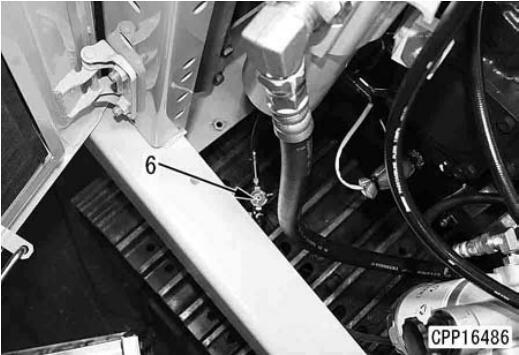
2.Loosen hydraulic oil drain plug (5) and drain the hydraulic oil.
6 Hydraulic tank: 90 l (Specified quantity of oil): 145 l
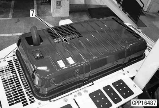
Open fuel drain valve (6) and drain the fuel. a After starting draining the fuel, open the fuel filler cap.
When fuel tank is full: 247 l
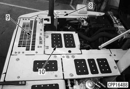
3.Open and lock engine hood (7)
4.Remove covers (8) – (10).
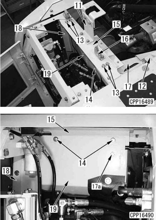
5.Remove bracket assembly (11).
6.Remove bracket (12).
7.Remove 4 upper mounting bolts (13) and 2 partition plate mounting bolts (14) and remove frame (15) and bracket (16) together.
8.Remove side covers (17) and (18).
Remove mounting bolt (17a) of side cover (17), too.
9.Remove partition plate (19).
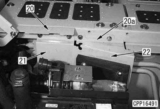
10.Remove brackets (20) and (20a) and partition plates (21) and (22).
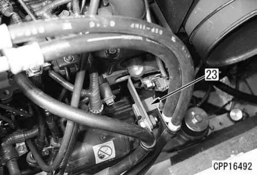
11.Disconnect the air conditioner compressor according to the following procedure.
Disconnect air conditioner hose clamp (23).
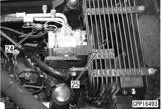
Disconnect wiring connector AC02 (24).
Remove air conditioner compressor belt protective cover (25).
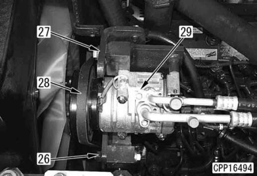
Loosen air conditioner compressor mounting bolt (26) and drive belt adjustment bolt (27) and remove drive belt (28).
Remove air conditioner compressor mounting bolt (26) and air conditioner compressor belt tension adjustment bolt (27) and disconnect air conditioner compressor assembly (29).
Move the air conditioner compressor assembly aside and bind it with a rope, etc. so that it will not be an obstacle.
12.Disconnect the hoses according to the following procedure.
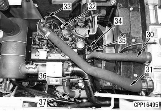
Disconnect radiator upper hose (30) from the radiator.
Disconnect aftercooler upper hose (31) from the aftercooler.
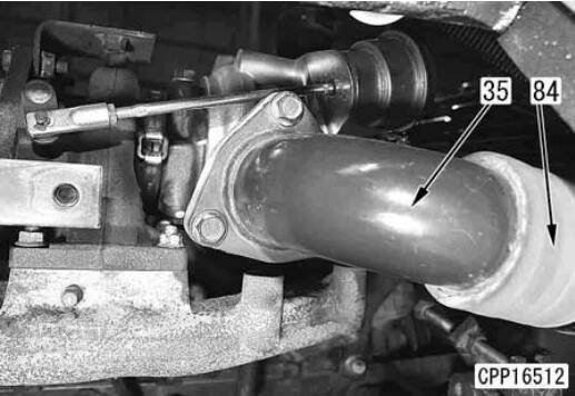
Disconnect 2 heater hose clamps (32) and disconnect heater hose (34) from water pump (35).
Disconnect hose (36) between the turbocharger and air cleaner from the turbocharger.
Disconnect connector (37) of the hose between the turbocharger and aftercooler from the turbocharger.
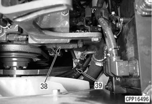
Disconnect radiator lower hose (38) from the water pump.
Since heater hose (39) is connected to radiator lower hose (38), disconnect them together.
13.Disconnect wirings according to the following procedure.
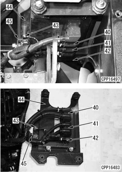
Disconnect engine controller wiring connectors ENG1 (40), CE02 (41) and CE03 (42).
Disconnect ground cable (43) from engine controller mounting bracket (44).
Disconnect ENG1 connector wiring clamp mounting bracket (45) and ENG1 connector wiring clamp together from engine controller mounting bracket (43).
The wiring of connector ENG1 (40) is tightened with wiring clamp mounting bracket (45).
The wiring clamp of connector CE02 (41) and CE03 (42) and controller mounting bracket (44) are tightened with wiring clamp bracket (45).
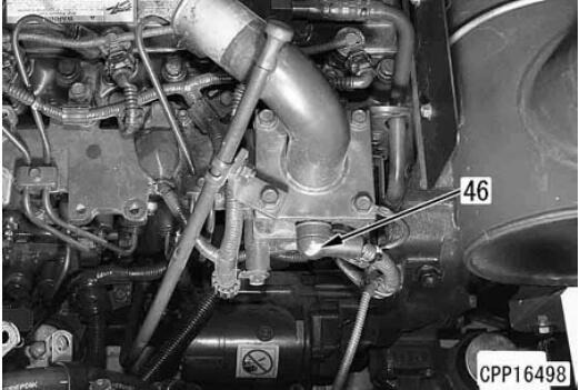
Disconnect electrical intake air heater wiring M23 (46).
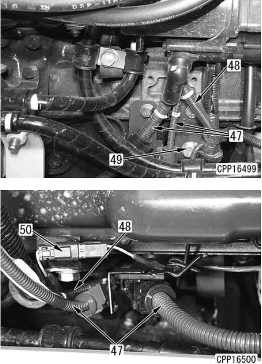
Disconnect starting motor wirings M20 (47) and M17 (48). [*9]
Disconnect starting motor wiring clamp (49).
Starting motor wiring M20 (47) is a pair of wire tightened together.
Starting motor wiring M17 (48) can be disconnected more easily from underside of the engine.
Disconnect engine oil pan oil temperature sensor connector (50).
Disconnect oil temperature sensor connector (50) from underside of the engine.
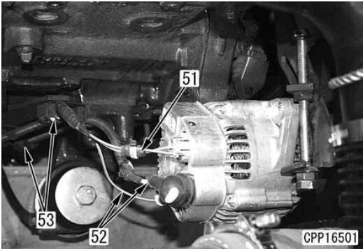
Disconnect alternator wirings M21 (51) and M22 (52). [*10]
Alternator wiring M22 (52) is a pair of wire tightened together.
Disconnect 2 wiring clamps (53).
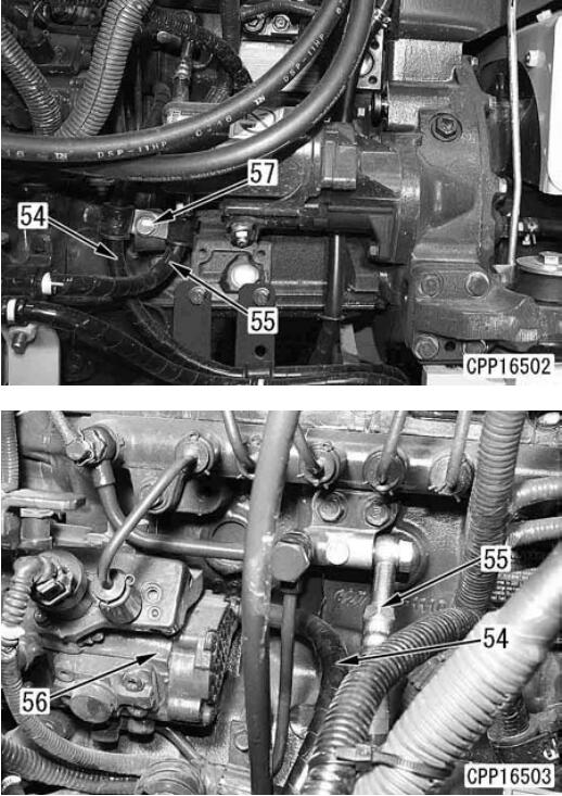
14.Disconnect fuel hoses (54) and (55) from fuel supply pump (56).
15.Disconnect fuel hose clamp (57).
16.Remove the fan assembly according to the following procedure.
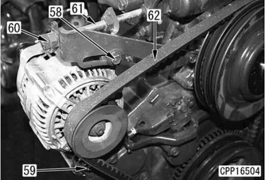
Loosen alternator mounting bolts (58) and (59).
Fully loosen alternator belt tension adjustment bolt (61) until the alternator belt can be removed.
Do not loosen double nut (60).
Remove alternator belt (62).
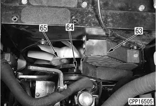
Remove fan guard (63).
Remove fan pulley mounting bolt (64) and remove fan and pulley assembly (65).
Place the removed fan and pulley assembly down.
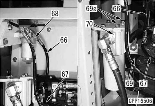
17.Remove the piping and wiring around the work equipment pump according to the following
procedure.
Disconnect hoses (66) and (67).
Disconnect attachment filter (68) and bracket together.
Disconnect damper case oil supply hose (69).
Disconnect hydraulic oil filter (70).
The damper case oil supply hose bracket is tightened with 2 mounting bolts (69a), too.
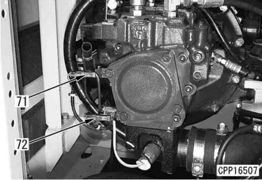
Disconnect connectors V11 (71) and P22 (72)
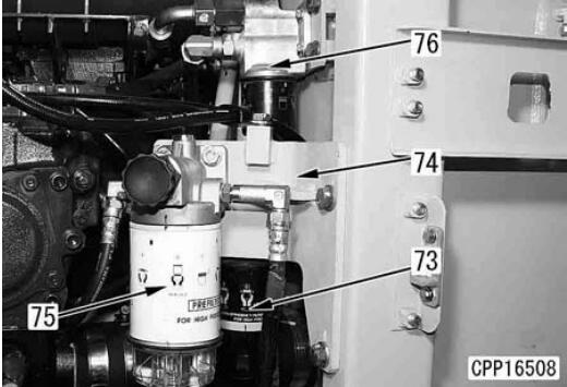
Disconnect fuel filter (73) from bracket (74).
Disconnect fuel prefilter (75) and bracket (74) together from the frame.
Disconnect engine oil filter (76) and bracket together from the frame.
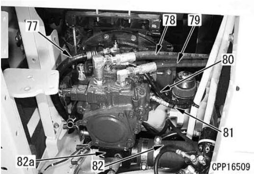
Disconnect 5 hydraulic hoses (77) – (81).
Disconnect suction hose (82) and elbow (82a) together from the pump.
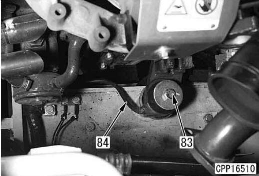
18.Remove 4 engine mounting bolts (83).
Remove ground cable (84) installed to the front right mounting bolt.
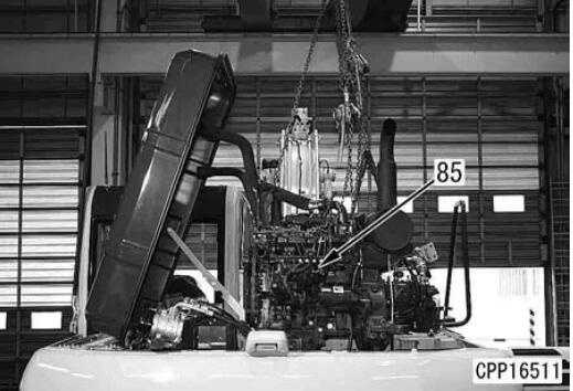
19.Lift off engine and work equipment pump assembly (85).
Installation
Carry out installation in the reverse order to removal.
[*1]
Hydraulic tank: 90 l
(Specified quantity of oil): 145 l
Start the engine, check the oil level, and add new oil if necessary.
[*2]
Fuel tank: 247 l
[*3]
For adjustment of the air conditioner compressor belt tension, see “Testing and adjusting air conditioner compressor belt tension”.
[*4] [*8]
Radiator hose clamping bolt:
(Both upper and lower hoses)
8.8 ± 0.5 Nm {0.9 ± 0.05 kgm}
[*5]
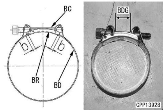
If air hose was disconnected from air connector of air intake manifold, install the MIKALOR clamp according to the following procedure.
Use a new clamp.
Align the hose to the original position (marking position).
Reference
Depth of insertion: 85 mm
Set the bridge (BR) under the clamp bolt and lap it over band (BD) at least (b) reaches 5 mm.
Do not use an impact wrench, when tighten the clamp.
2 Clamp bolt (BC): Lubricanting oil (THREEBOND PANDO 18B)
When reusing the hose
Install the clamp to the clamp mark made on the hose.
3 Tighten to torque of at least 6 Nm {0.6kgm}
When using a new hose
Tighten until dimention (BDG) is 7 – 10 mm. (aftercooler side) 0 – 3 mm. (turbocharger side)
[*6]
Air hose clamping bolt:
10.5 ± 0.5 Nm {107 ± 5 kgm}
[*7]
If air hose (84) was disconnected from air connector (35), install the MIKALOR clamp according to “[*5] Installation procedure for MIKALOR clamp”.
Depth of insertion: 65 mm
[*9]
Starting motor wiring terminal mounting bolt:
(M17) 2.6 – 6.6 Nm {0.27 – 0.68 kgm}
(M20) 17.7 – 24.5 Nm {1.8 – 2.5 kgm}
[*10]
Alternator wiring terminal mounting bolt:
(M21) 5.9 – 9.9 Nm {0.6 – 1.0 kgm}
[*11]
For adjustment of the alternator belt tension, see “Testing and adjusting alternator belt tension”.
[*12]
If hose (82) was disconnected from elbow (82a), install the MIKALOR clamp according to
the following procedure.
Tighten the clamp on the inside of the hose first and then tighten the clamp on the hose side (elbow side).
Then, referring to “[*5] Installation procedure for MIKALOR clamp”, tighten the hose clamp.
[*13]
Engine mounting bolt: LT2
Engine mounting bolt:
235 – 285 Nm {23.5 – 29.5 kgm}
Target: 279.6 Nm {28.5 kgm}