Kubota diagmaster software is special diagnostic software for Kubota machine.In this post,car-auto-repair.com will show you guide on how to configure DST-i interface for Kubota Diagmaster software.
Preparations:
2022 Kubota Takeuchi Diagmaster v22.08.01 v4.1.2 Software Free Download
Kubota EPC Spare Parts Catalogue 2021.06 Download
Original Kubota DST-i Diagnostic Tool
Main Contents:
1.Diagnostic Connector Positions
2.Diagnostic Tool Connection Procedure
3.Checking the communication operation of the Interface(DST-i)
4.Checking the Operation of the ECU
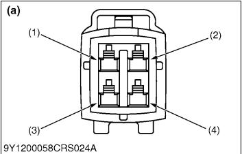
1.Diagnostic Connector Positions
Refer to the operator’s manual for your Kubota machine to check the position for connecting the diagnosis tool.
(1)Terminal IG-SW (V13, V33) (2) Terminal CAN1-H (V36)
(3) Terminal S-GND (V60) (4) Terminal CAN1-L (V16) (a) CAN1 Connector
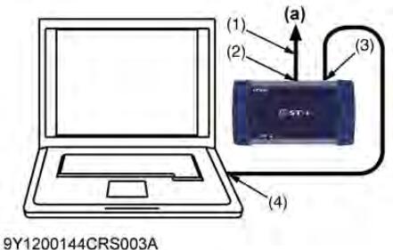
2.Diagnostic Tool Connection Procedure
IMPORTANT
• At first time usage, it is necessary to do “Communication Setting” with administrator user account.
• Prepare a PC on which the diagnostic software has already been installed.
• When connecting the diagnosis cable, ensure that the key switch on the machine side is OFF.
1.Start up a PC on which the diagnostic software has been installed with administrator user account.
2.Connect the machine-side CAN1 connector (a) to the interface connector (To Machine) (2) with the cable (To Machine) (1).
3.Connect the cable (USB) (4) to the USB connector (To PC) (3) and then connect the USB cable to the USB port on PC.
4.Start the diagnostic software.
5.Select “Communication Setting” from “System Setting” in the menu and execute. (Only when performing the initial settings.)
NOTE
• The USB port used while the “Communication Setting” process, should always be used.
(1) Terminal IG-SW (V13, V33)
(2) Terminal CAN1-H (V36)
(3) Terminal S-GND (V60)
(4) Terminal CAN1-L (V16)
(a) CAN1 Connector
(1) Cable (To Machine)
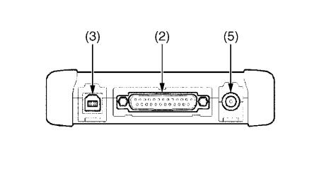
(2) Interface Connector (To Machine)
(3) USB Connector (To PC)*
(4) Cable (USB)
(5) DC Jack (Reserved)*
(a) CAN1 Connector
* Rubber cap is attached to USB connector and DC jack each
3.Checking the communication operation of the Interface(DST-i)
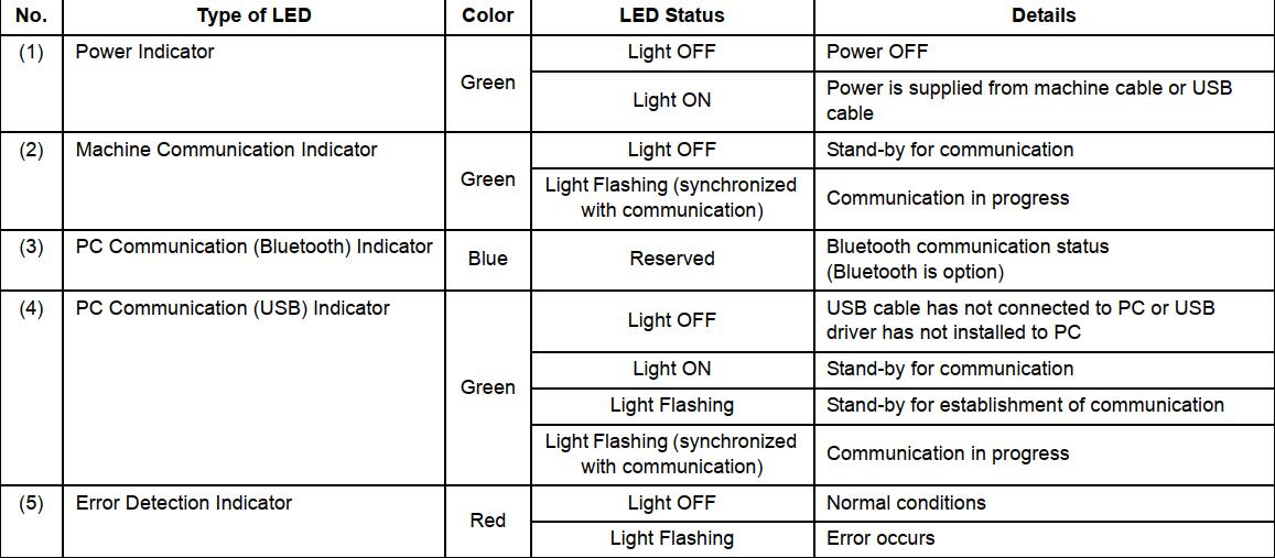
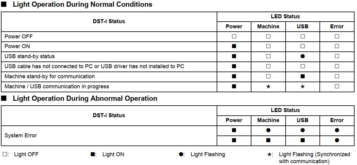
The communication operation can be checked with the illuminating condition of the five indicators on the DST-i unit.
If a communication error occurs, check the illuminating condition of each indicator and repair or replace the malfunction (including cable open circuits).
DST-i operation Status and Display Specification
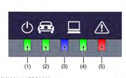
1)Power Indicator
2)Machine Communication Indicator
3)PC Communication (Bluetooth) Indicator
4)PC Communication (USB) Indicator
5)Error Detection Indicator
DST-i operation Status and Display Specification
4.Checking the Operation of the ECU
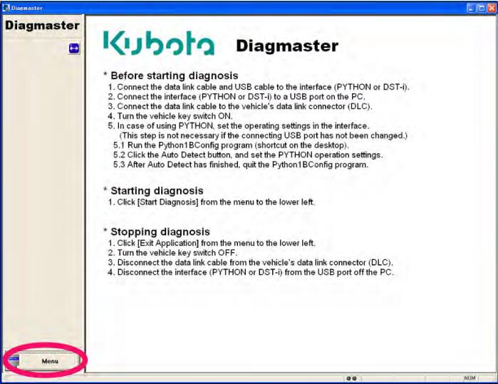
Starting Diagmaster
Double-click the Diagmaster icon on your computer desktop
Enter your “User ID” and “Password”, and then click the button.
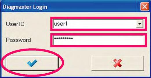
The Diagmaster initial screen appears
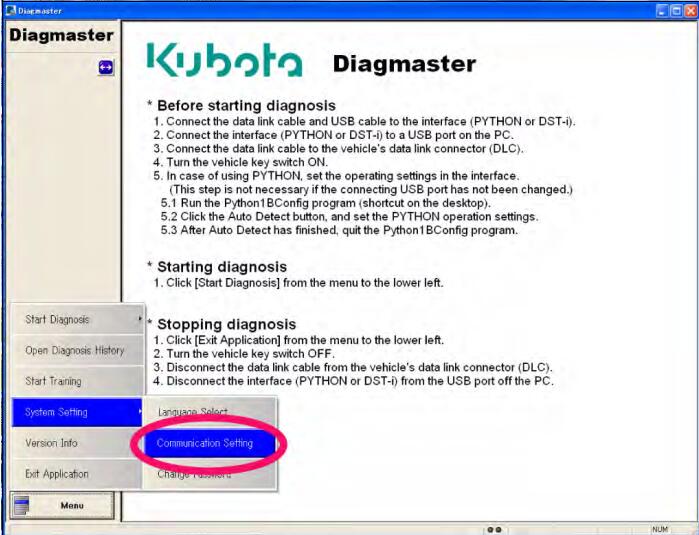
DST-i Communication Settings
From the “Menu”, select “System Setting”, and then “Communication Setting”
Click the interface select button.
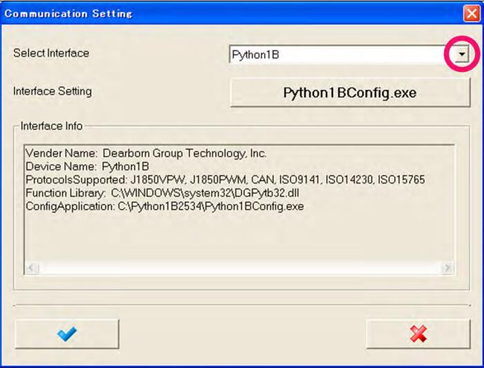
Select “DST-i”, and then click the mouse button.
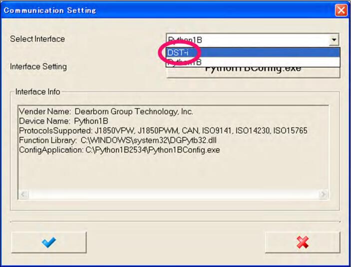
Click the “OK” button.
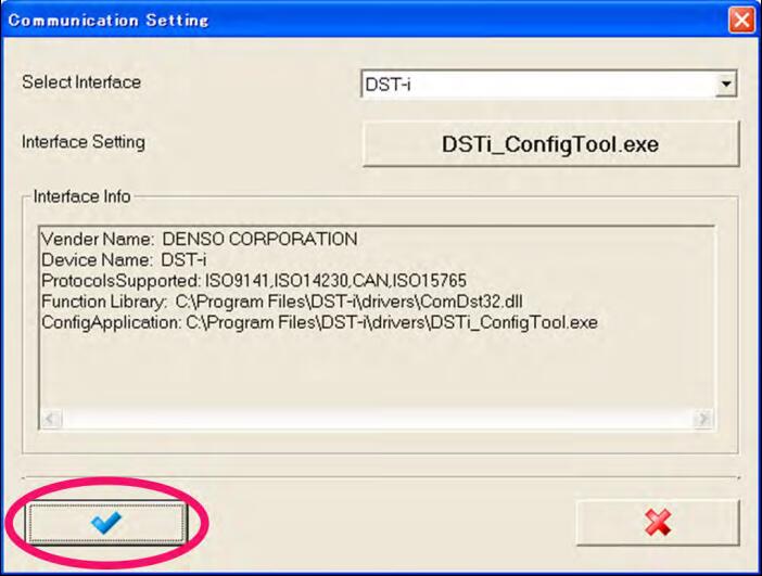
NOTE
If you failed in the setting, confirm the connection and start again from procedure 1. to 4.
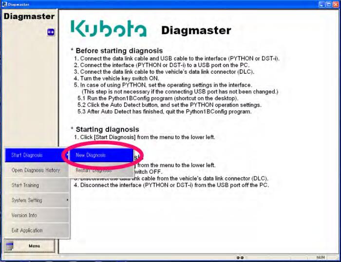
From “Menu”, select “Start Diagnosis”, and then “New Diagnosis”
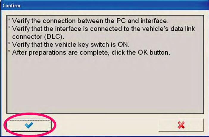
Click the “OK”button.
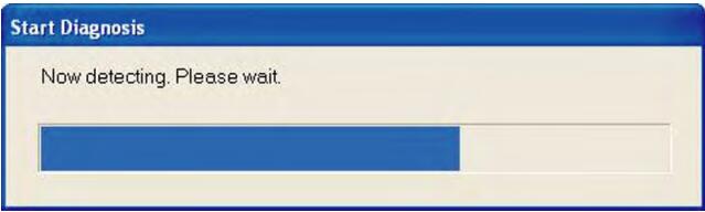
The transmitting to ECU progress indicator appears
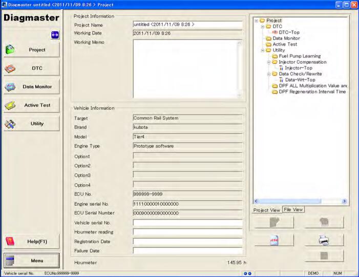
The “Project” screen appears
NOTE
• If you failed in the setting, confirm the content of procedure 6. and start again from procedure 5. to 8.