After you control valve repairing for New Holland T6030 tractor,it is necessary to assemble it.So here car-auto-repair.com show you guide on how to assemble control valve for New Holland T6030 tractor.
Related Contents:
2024 CNH EST 9.10 9.2New Holland Diagnostic Software Free Download
New Holland Agricultural & Construction Parts+Service Manual Free Download
Procedures:
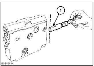
1.Prior to inserting control valve spool in housing ensure flats (1) on end of spool are in vertical position as shown, then install the load holding check valve, as described below. Do Not rotate spool after installing load holding valve otherwise damage to spool and load holding valve plunger will occur
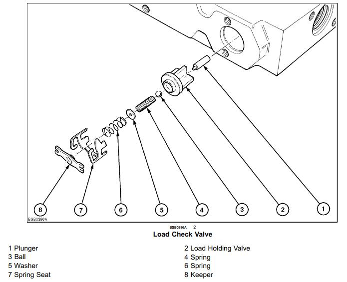
Load Holding Check Valve installation
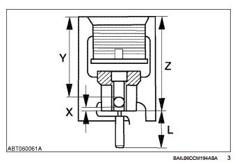
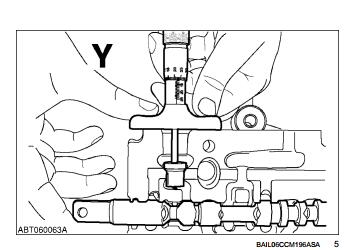
2.Dimensions:
L = Plunger Length
Z = Depth to the Plunger
Y = Depth to the Pilot Ball
B = Pilot Ball diameter ( 4 mm (0.16 in)
X = Gap between the Plunger and the Pilot Ball
NOTE: When the control valve is in the neutral position there must be a gap (X) 0.2 – 0.3 mm (0.008 – 0.012 in) between the plunger and the pilot ball.
Calculating Gap (X)
3.Install the shortest plunger (No rings , 15.07 mm (0.59 in)) in position with the control valve in neutral.
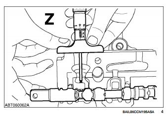
4.Measure dimension ‘Z‘ from the top of the plunger to the top face of the remote valve body (e.g. 36.43 mm (1.43 in) ).
5.Remove the plunger.
6.Install the load check valve and the pilot ball. Ensure that both are fully seated
7.Measure dimension ‘Y‘ from the top of the ball to the top face of the valve body (e.g. 36.43 mm (1.43 in))
Load Check Valve Installation
8.Ensure that the control spool is in neutral.
9.Install the determined plunger using long nosed pliers
10.Install the lock valve , pilot ball, pilot spring, washer and the spring (Refer to Figure 2)
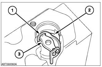
11.Use a screwdriver to bend both retainer lugs (1) (figure 5) upwards, and locate the retainer to the bore.
12.Fit the spring seat into the retainer, straighten the lugs and turn the assembly anti clockwise 90 ° to secure in the remote valve bod
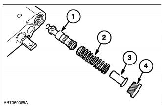
Flow Control Valve Installation
13.Install the flow control spool valve (1), together with the spring (2) , guide (3) and retaining plug (4) .
Tighten the retaining plug to a torque of 67 Nm (49.42 lbft)
Lift Check Valve Installation
14.Check the bore for any rough edges and smooth if necessary
15.Install the check valve (1) into the remote valve body.
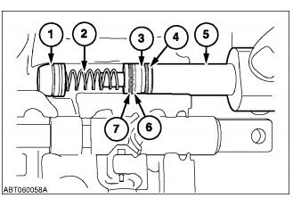
16.Fit the back up ring (6) and the ’O’ ring (7) in the groove in the retainer (3) and locate the spring (2) onto the inner spigot of the retainer.
17.Locate the snap ring (4) , retainer and spring assembly onto the installation tool 380002720 (5) .Install the assembly into the remote valve bore and push until the tool handle contacts the remote valve body.
18.The snap ring must be located in the groove. Ensure that the retainer is located up against the snap ring .
Install a new plastic cap.
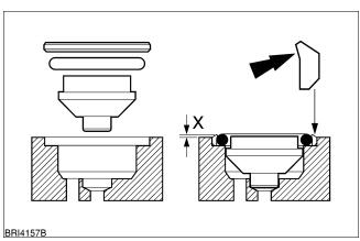
Load Sense Check Valve Installation
19.Install new ’O’ Ring seal and back up ring
NOTE: Clearance ’X’ should be approximately 0.5 mm (0.020 in) from the flange face of the valve segment to the top edge of the inserted check valve.
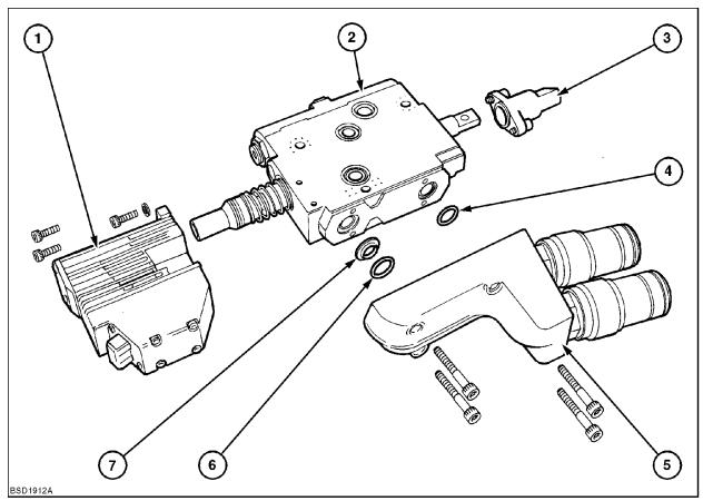
20.Assemble Spool control unit , coupler housing and spool cap to the assembled valve slice .

More repair cases for New Holland machine,please refer to:New Holland Trouble Repair