The mod is conversion of a EU Fxx 523i to a 528i. It is valid for cars of production period where both models were delivered with the same N53 motor, albeit the 523i being detuned in HP & Torque.
The mod requires a software change to the DME & EGS modules of the car, and a replacement of the Single-step intake manifold with a 3-Step intake manifold equipped by DISA valves.
This document details the software change segment of the mod.
Module software used is the same as the original delivered by BMW in MY51 N53 equipped cars.
Flashing ECU’s with E-sys is not a technically complicated process and the risks involved are less of technical nature and more of integration & configuration mistakes. Successfully passing the flashing process itself needs some precautions & guidelines which are general to any eeprom style programming:
- Maintain constant power supply to the programming & target devices
- Allow sufficient time for processing to complete
- Stop in case of errors and analyze/troubleshoot the reasons before proceeding
- Use the programming tool built-in controls to assure proper processing
The E-Sys tool itself has powerful controls to avoid flashing mistakes when it comes to compatibility between the software to be flashed & the target ECU. The ECU’s themselves being of automotive grade are by nature of robust fail-safe design, especially those related to engine, transmission, car security & passenger safety.
E-Sys also provides the integration support by managing the Master Security Module (MSM) of the car to maintain security & compatibility in programming.
The controls in the hands of the user however, do allow for a lot of manual manipulation which can lead to failed, incorrect flashing and a non-functioning car.
The risk therefore in this process, is mitigated mostly by keeping strict planning & control, understanding the integration of the change within the car-wide computerized network, being vigilant in troubleshooting unexpected failures before making new attempts and finally making sure that the E-Sys settings and functions are carefully and correctly set.
Mandatory Prerequisites:
Confirm current ECU part numbers and target ECU part numbers are identical based on realoem / ETK. Here we were ok with the DME, but had difference in EGS module. Posted question to BMW technical staff who confirmed the difference is for support/replacement related reasons. Units are identical.
No exchange of modules. Units are functional and in-sync with car network. No faults registered in the fault or Information memories.
- Know your Shipment & Current I-Step. Refer to basic coding guide to read I-Step from VCM.
- Car network is running a unique I-level across modules.
- PSdZdata for current I-level available and imported into Esys.
- FA in car is in shipment status ie. Zeitkriterium not modified.
- Car hooked up to battery charger or maintainer.
Esys Guide:
How To Use BMW E-sys Coding Software
E-SYS BMW Coding Functions List
BMW E-sys program BMW F-series FA Guide
BMW E-sys Coding Software Installation Guide
BMW Coding/Flashing/Progrmming PDF+Video Guide
Phase 1: Connection
1.Prepare PC. Make sure wifi & bluetooth are disabled and no application is running.
2.Connect ENET cable to OBD port then to RJ45 port on PC.
3.Car ignition on, engine off.
4.Start-up E-Sys. After up to 30 seconds the car and your PC are on the same IP subnet.
5.Click on the ‘Connect‘ button.
6.In the ‘Open Connection’ window which appears, select the appropriate TargetSelector.
7.Project is the Fxx I-Step of PSdZdata you loaded into Esys, VehicleInfo is your car Fxx without DIRECT at the end.
8.In the Interface section, select ‘Connection via VIN’.
9.In the Vehicle-specific parameter section, select ‘Read parameters from VCM‘.
10.Click Connect.
11.A pop-up window will appear. Confirm what you see is your known Shipment I-step & click OK.
Phase 2: Confirm current FA and SVT Actual state match to PSdZdata
1.Go to Comfort mode – TAL-Calculating. Top-left ‘Vehicle Order’, select ‘Read‘. After VO is read, Open the FAList tree to FAList/FA/FZAuftrag/Type and confirm the ‘Zeitkriterium’ entry is your shipment (mmyy format) & the ‘Typschlüssel’ entry is your production code MT11. Click save and provide a clearly identifiable name eg. FA_ORG_MT11_yyyymmdd Right click on the ‘FA’ folder and select ‘Activate FA‘.
2.On the right, in ‘SVT Actual’ section, select ‘Read SVT’. When done, The SVT ECU tree will appear on the left. All entries will be BLUE in color. Click save and provide a clearly identifiable name eg. SVT_ACTUAL_MT11_yyyymmdd
3.On the right, in ‘KIS/SVT Target section, perform the following: In ‘Calculation Strategy’ select ‘Complete Flash’. In I-Step (shipm.) select your I-Step Shipment as verified by connection phase step 11. In I-Step target should be only one entry, matching to the Target selected in connection phase step 7. Click ‘Calculate‘ and wait. When done, The SVT ECU tree entries on the left will change color.
The entire tree with all entries must be BLACK with exception of SWUP, ENTD & NAVD entries in the CMB_ECALL/CMB_MEDIA/HU_CIC modules which may remain BLUE.
Phase 3: Edit & write FA to car
1.Modify production code from MT11 to MY51 by editing the ‘Typschlüssel’ to Production code MY51.
2.Save and provide a clearly identifiable name eg. FA_TARGET_MY51_yyyymmdd
3.Write FA to VCM.
Refer to basic coding guide for editing and writing FA to VCM.
Phase 4: SVT Target calculation for modified FA
1.Go to Comfort mode – TAL-Calculating. Top-left ‘Vehicle Order’, select ‘Load‘. Open your modified VO file (eg. FA_TARGET_MY51_yyyymmdd). Right click on the ‘FA’ folder and select ‘Activate FA’.
2.On the right, in ‘SVT Actual’ section, select ‘Load‘. Select your SVT Actual created in Phase 2 (eg. SVT_ACTUAL_MT11_yyyymmdd). The SVT ECU tree will appear on the left.
3.On the right, in ‘KIS/SVT Target section, perform the following: In ‘Calculation Strategy’ select ‘Complete Flash’. In I-Step (shipm.) select your I-Step Shipment as verified by connection phase step 11. In I-Step target should be only one entry, matching to the Target selected in connection phase step 7. Click ‘Calculate‘ and wait. When done, The SVT ECU tree entries on the left will change color.
4.Click save and provide a clearly identifiable name eg. SVT_TARGET_MY51_yyyymmdd.
The entire tree with all entries must be BLACK with the following exceptions:
1.SWUP, ENTD & NAVD entries in the CMB_ECALL/CMB_MEDIA/HU_CIC modules which may remain BLUE.
2.Entries for the DME & EGS modules may appear RED.
Phase 5: SVT target validation
This is one of the two most important steps in the process. We visually validate the SVT Tree for the changes we want to do and verify that all our prerequisites are in order. The validation assumptions & expected results are as follows:
Only the DME & EGS modules should have a mix of BLUE & RED entries. All entries on all other modules must be either BLACK or BLUE.
- On both DME & EGS, the ONLY entries ALLOWED to be RED are BTLDx, SWFLx & CAFDx.
- All entries starting with HWxx MUST be BLACK.
- There may be one or multiple SWFL changes for each module. That is ok.
- There may or may not be a BTLD change for a module. That is ok.
- There may or may not be a CAFD change for a module. That is ok.
Here is an example snapshot from the SVT tree with Actual & Target calculation. I-step F010-12-11-503. DME:
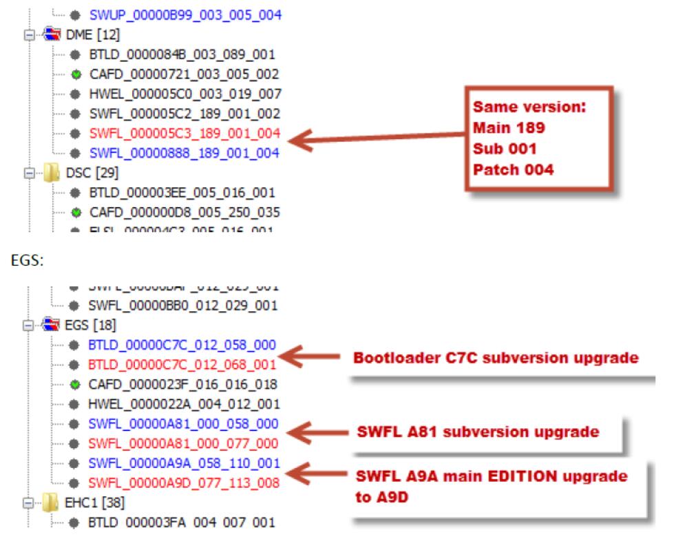
The changes we expect are as follows:
DME SWFL – current firmware with ID 888 will be replaced with SWFL firmware ID 5C3, from the same Main, Sub & Patch versions.
- EGS BTLD –current bootloader with ID C7C be upgraded to other Subversion & Patchversion branch.
- EGS SWFL –current firmware with ID A81 will be upgraded to other Subversion & Patchversion branch.
- EGS SWFL –current firmware with ID A9A will be replaced with SWFL firmware ID A9D, from other Main, Sub & Patch versions.
Once we are satisfied with all validation assumptions, we can proceed with the next step.
Phase 6: TAL calculation
- In the Tal-Calculation window, on the right, in the ‘TAL’ section, make sure nothing is checked. Click ‘Calculation’ and wait.
- When finished, click save and provide a clearly identifiable name eg. TAL_TARGET_MY51_yyyymmdd
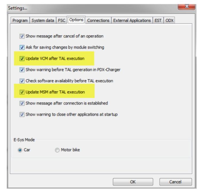
Verify Esys settings
Go to Options-Settings menu.
On the Settings windows, select ‘Options’ tab and confirm all entries are checked.
The relevant and extremely important entries for this process are ‘Update VCM after TAL execution & ‘Update MSM after TAL execution’.
Phase 7: TAL processing DME & EGS
- Go to Expert mode –TAL Processing.
- As TAL –select your TAL_TARGET_MY51_yyyymmdd
- As SVT –select your SVT_TARGET_MY51_yyyymmdd
- As FA –select your FA_TARGET_MY51_yyyymmdd
- Click ‘Check software availability’& get positive response that all is available.
- Log tab –select ‘Events’and keep Type ALL.
- Parameters tab –all options selected, option 4 on Merge with existing InstalledECUList, both ‘Switch gateways’selected & empty.
- ECU tab –should list 2 lines for DME & EGS only.
- UNCHECK the top-left ALL box to REMOVE all selections.
- ONLY on DME line, Select ONLY ‘blFlash’& ‘swDeploy’& ‘cdDeploy’
- Visually confirm AGAIN that nothing is selected except the ‘blFlash’& ‘swDeploy’& ‘cdDeploy’ on the DME line.
- Click START and wait.
- A window will pop up to confirm the three I-Step levels in the VCM. Do not change it & Click OK.
- Once processing starts, the E-Sys window will be non-responsive for a few seconds eg. if you want to browse at the log. Just give it a few seconds, and the log tab will appear and show progress. The flashing process only takes a couple of minutes, you will notice the percentage hang a while at 0% then it will start to increase. This is normal.
- There is no ‘processing ended’or any pop up that indicates the job is done. Wait until you see on the log window the message that confirms VCM Update: finished.
Once done, disconnect E-sys from car and power off the ignition. Disconnect the battery charger/maintainer from the car and attempt to start the car. If the car starts, the DME flash was successful and can proceed to flashing the EGS module.
It is highly recommended to restart E-Sys for the EGS flash.
Following a successful connection, repeat Phase 7 above with one difference steps 10 & 11:
- ONLY on EGS line, select ONLY ‘blFlash’& ‘swDeploy’& ‘cdDeploy’.
- Visually confirm AGAIN that nothing is selected except the ‘blFlash’& ‘swDeploy’& ‘cdDeploy’ on the EGS line.
Once the EGS flash is completed, the procedure is over, and your car DME & EGS modules have been converted to Production Code MY51.
Troubleshooting
If there were no errors logged during DME flash but the car does not start after DME flashing, it likely means that the alternative SWFL ID used does not match the installed hardware.
If this happens, it is recommended to attempt reverting back to the original DME SWFL ID by loading and activating the ORIGINAL FA_ORG_ MT11, reading the current SVT from the car, calculating a temporary SVT_TARGET & a new TAL. If the calculations are correct, the TAL will have only one line in the flashing window – for DME. Execution of this TAL should revert the car to its original state.
The revert flashing procedure is essentially the same as listed earlier in Phase 7, albeit using the newly generated files above.
Other observations
It was identified that multiple fault errors are registered in the car Fault memory during flashing.
During the TAL processing, the KOMBI & HU_CIC showed multiple system errors related to DSC, degraded braking system, Restraint system, SOS calling and various others.
Faults were registered in other modules that are linked to the DME & EGS via the MOST network.
ISTA/D was able to clear all the faults. Users can use ISTA/D, INPA & Tool32 to clear them too.
This conversion is only useful in conjunction with replacing the intake manifold with the 3-stage manifold delivered on Production code MY51 cars.
Until the new manifold is installed, new faults will continue to register and the CEL light will be on.
In case of failures, difficulties or unexpected results, please contact the forum members for assistance.
Also, please consider that E-Sys does not provide:
- Initialization procedures that may be required to run following software change.
- Fault errors display that may be registered in the ECU fault memory during or after TAL processing.
- The necessary tools for performing required follow-up procedures or fault clearing.
We have not observed any initialization or normalization procedures needed after flashing the DME & EGS.
No token or patch is needed for any steps in this guide.