This instruction show you guide on how to remove engine for CLARK Forklift C500 models.If you need more service info,please refer to:Clark Forklift Workshop Service Manual 2020 Download
Related Content:
2020 Clark ForkLift Parts Pro Plus EPC V500 V444+KG Free Download
Procedures:
1.Park truck on a level surface.Chock front and back wheels.Lower forks to floor.Set parking brake.
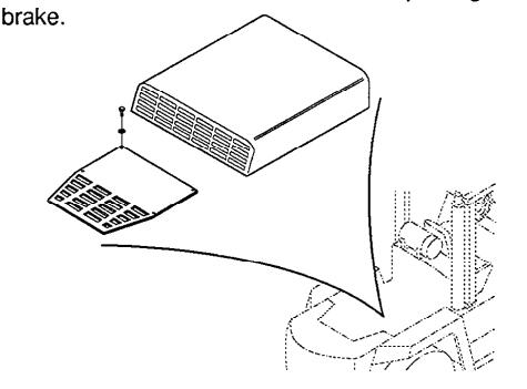
2.Remove hood and counterweight grill.
3.Remove positive and negative battery cable from engine and battery cables from battery.
Warning:
Whenever disconnecting battery cables, always disconnect negative ground terminal first.
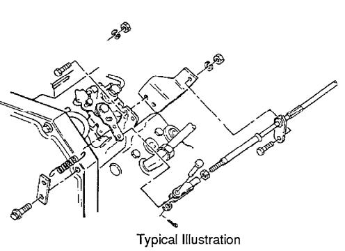
4.Disconnect accelerator cable from engine fuel pump and from cable support bracket.Lay cable back where it will be out of the way when engine is lifted out.
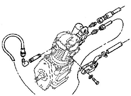
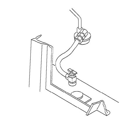
5.Disconnect air brake lines from air compressor as shown.
DANGER:
Depressurize air system by applying brakes until gauge reads zero pressure.Severe injury or death can result if air system components are removed while system is still pressurized.
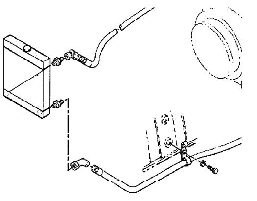
6.Disconnect transmission cooling lines at oil cooler and radiator.Cap or plug exposed fittings or ports.Remove cooling line supporting clip and lay hose back where they will not interfere with engine removal.
7.Remove radiator cap.Place a large drain pan which has a minimum capacity of 27 quarts [25.5liters] under the radiator and engine and drain coolant from radiator and engine.Dispose of coolant in prescribed manner.Do not reuse.
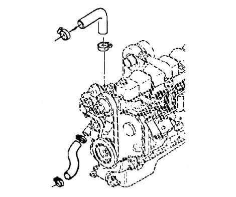
8.Disconnect engine coolant hoses.Remove radator and cooling fan.
9.Shut off fuel supply at fuel tank.Disconnect fuel supply and return lines at engine.Use suitable container to catch fuel drainage.Cap or plug exposed fuel line fittings.
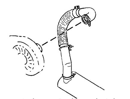
10.Disconnect exhaust system from engine turbo-charger.
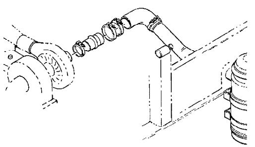
11.Disconnect air intake assembly at engine turbo-charger and at air cleaner and remove.
12.Disconnect all electrical wiring between engine and truck.Tag each wiring terminal to assist in reconnecting.
13.Drain oil from engine using a suitable container.
Dispose of used oil in approved manner.Do not reuse.
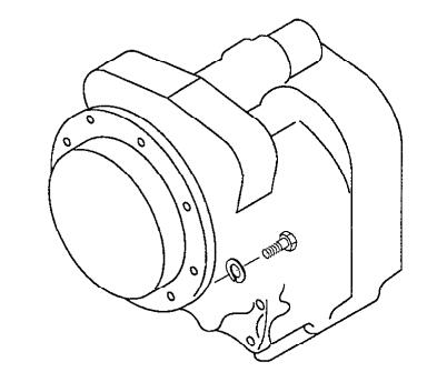
14.Remove cap screws holding transmission bell-housing to engine bell housing.Leave transmission on cross member mounting bracket assembly.
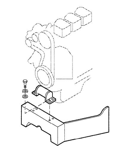
15.Remove engine mount to frame bolts, flat washers and nuts.
16.Attach suitable lifting device to engine lifting eyes and remove engine from truck. It will be necessary to move engine 4 to 5 inches towards counterweight to disengage it from transmission. Place engine on approved stand.
17.Service for the Cummins Diesel engine is provided only by Cummins. Consult your nearest Cummins distributor for assistance. If necessary, your Clark dealer can assist you with this.
18.If it is necessary to remove ring gear and backing ring from flywheel for engine repair it must be reinstalled in the following manner.
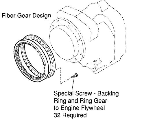
19.The special screw is to be used for ONE installation only.If the screw is removed for any reason it MUST BE REPLACED.Obtain genuine replacement parts from your Clark dealer.It is recommended that the epoxy left in the flywheel hole be removed with the proper tap and cleaned with solvent.Dry hole thoroughly and use a NEW screw for re-installation.
Install backing ring and thirty-two(32) special screws to approximately.06 inch [1,5 mm] of seated position. It is permissible to use a power wrench for this installation phase. With a calibrated torque wrench tighten screws to 23-25 lb ft of torque [31,2-33,8N·m].
NOTE:Assembly of the ring gear must be completed within a fifteen minute period from start of screw installation.The screws are prepared with an epoxy coating which begins to harden after installation in the flywheel mounting holes.If not tightened to proper torque within the fifteen minute period insufficient screw clamping tension will result.
To obtain maximum effectiveness of the special screw’s locking feature,a minimum time period after screw installation of twelve(12) hours is suggested before engine start-up.
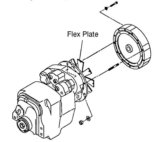
20.Beginning with lot 8518, Clark changed the fiber gear design shown above(17.) to a flex plate design as shown above. Refer to Group 06-Transmission for details on mounting of flex plate.
21.Reinstall engine in reverse order.
Torque front engine mount bolts to 60-65 lbf-ft[81-88N·m].
Torque flywheel housing bolts to 30-33 lbf-ft [40-45 N·m].