This article show a guide on how to install 302A adaptive cruise control (ACC) for Ford F150 XLT.Prior to beginning, using FORScan or equivalent, check for any DTCs that may be present in any modules. Document the DTCs and clear. This step will assist in identifying any DTCs that were/were not created as a result of the following procedure.
Required Hardware:
● (2) W520802-S900 Nut Flanged M6 – Bracket to Bumper Stop
● (2) W505424-S900 Bolt & Washer As. (Hex Head) M6 x 1.0 x 20MM – Bracket to Bumper
● (3) XL3Z-17E971-AA Retainer – Cruise Control Module Bracket to Bumper
● (1) FL3Z-14C022-A Bracket – Distance Sensor
● (3) W705817-S441 Nut M6 – Sensor Stud
● (1) W717468-S439 Stud M6 x 28 + M6 x 23 – Sensor Alignment
● (2) W717467-S439 Stud M6 x 36 + M8 x 12 – Sensor (Bottom Two)
● (1) FL3Z-19G468-A Module – Vehicle Emergency Message / Heads Up Display
● (1) FL3Z-15043C54-BA Cover As. – Heads Up Display Module Trim
● (1) FL3Z-15K867-F Harness (5.0L only) – Parking Distance Aid Sensor
or
● (1) FL3Z-15K867-B Harness (3.5L only) – Parking Distance Aid Sensor
● (1) FL3Z-9E731-D (Motorcraft Part # DY-1395) Sensor As. – Speed
o (3) W790214-S300 Grommet – Sensor (Cruise Control Module)
● (1) FL3Z-9C888-BA (Motorcraft Part # SW-7450) Switch – ACC Steering Wheel
● (12) W714030-S424 Retainer (Clip) – Front Bumper Cover
● (3) W714076-SS3JA Push Pin – air deflector to bumper
● (1) EU2Z-14421-CA (Motorcraft part # WT-1013) Terminal – C134 Connector – required for 5.0L only
● Motorcraft Threadlock 262 TA-26 or equivalent
Before Beginning:
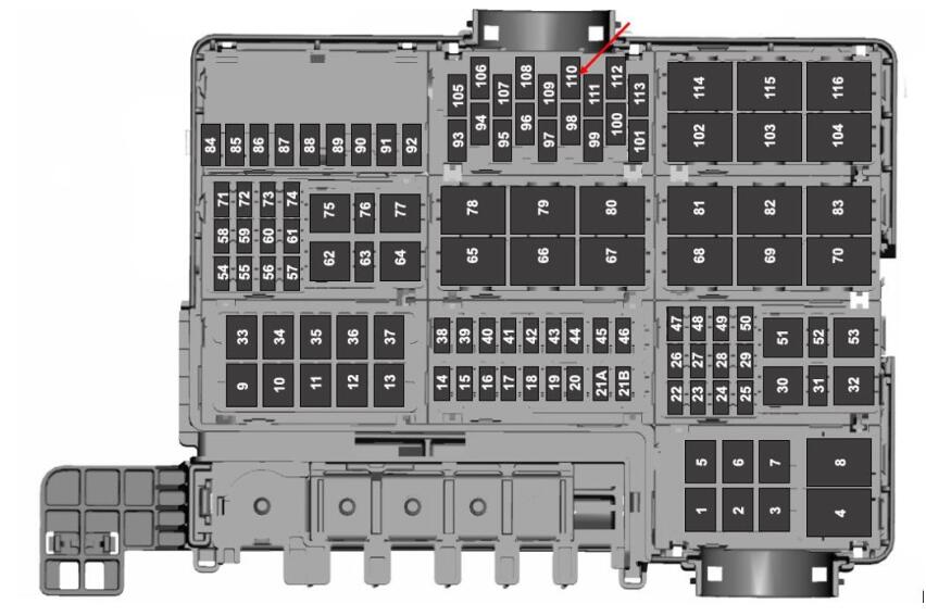
● Confirm the presence of 10 amp fuse at location # F110 in the Power Distribution Box (Battery Junction
Box – BJB). This fuse provides 12V+ to the Cruise Control Module. This fuse should be present if vehicle is equipped with a 4×4 Transfer Case Control Module (TCCM).
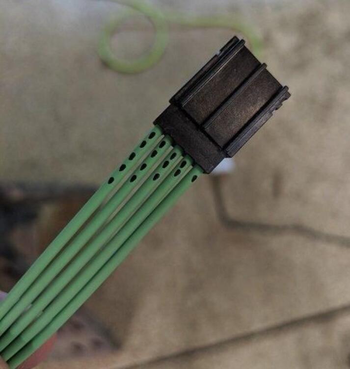
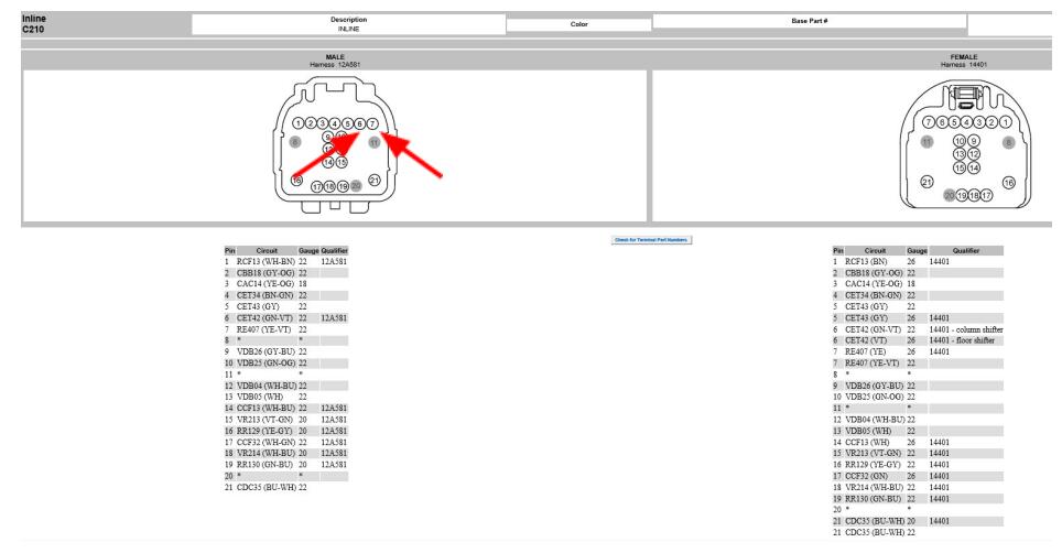
The C134 16 pin inline connector is located behind the RH headlamp. Confirm the presence of 4 wires in the 12A581 chassis harness:
• GN-OG / VDB25 (HS2 CAN +) at location # 1 of C134 male connector of the 12A581 Chassis harness.
• GY-BU / VDB26 (HS2 CAN-) at location # 2 of C134 male connector of the 12A581 Chassis
harness.
• BK-GY / GD131 wire (12V-) at location # 8 of C134 male connector of the 12A581 Chassis harness.
• YE-BU / CBBB0 wire (12V+) at location # 10 of C134 male connector of the 12A581 Chassis
harness **.
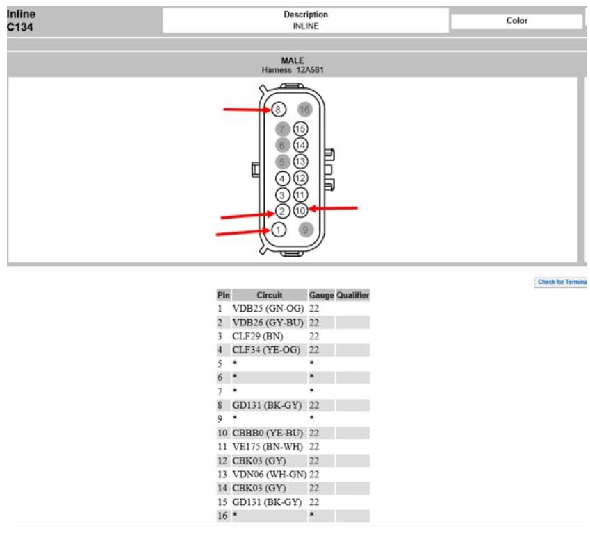
** Note: if YE-BU / CBBB0 wire is not present at location # 10 of the C134 connector of the 12A581 chassis harness, an alternate 12V+ switched power supply must be sourced at any (1)
of (3) locations depending on vehicle configuration:
1All vehicle configurations – Tap into the YE-BU / CBBB0 switched/fused (F110) wire at either the BJB (Battery Junction Box) or TCCM (Transfer Case Control Module) and add (1) EU2Z-14421-CA
(Motorcraft Part # WT-1013) terminal to location # 10 of the C134 connector of the 12A581 chassis harness.
2On 2.7L & 3.5L Ecoboost vehicles – switched/fused (F97) 12V+ can be sourced at the 15K867 Fog Lamp & Cruise Control harness by tapping into either of the (2) GY / CBK03 wires for the EBOV or Lower Active Grille Shutters
3On 5.0L vehicles – switched/fused (F97) 12V+ can be sourced at the 12A581 chassis harness by
tapping into the GY / CBK03 wire at the C1651 connector for the Upper Active Grille Shutters and add (1) EU2Z-14421-CA (Motorcraft Part # WT-1013) terminal to location # 10 of the C134 connector of the 12A581 chassis harness.
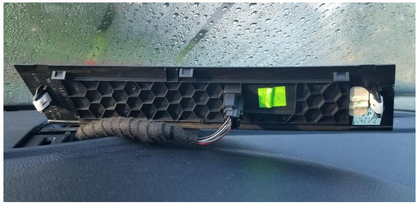
● Confirm the presence of the C2395 5 pin connector for the Heads Up Display (HUD) Module Using a non-marring tool, release the tabs on the trim panel and set aside. Is the C2395 harness connector attached to the trim panel?
Adding the C2395 HUD Module Connector & Harness
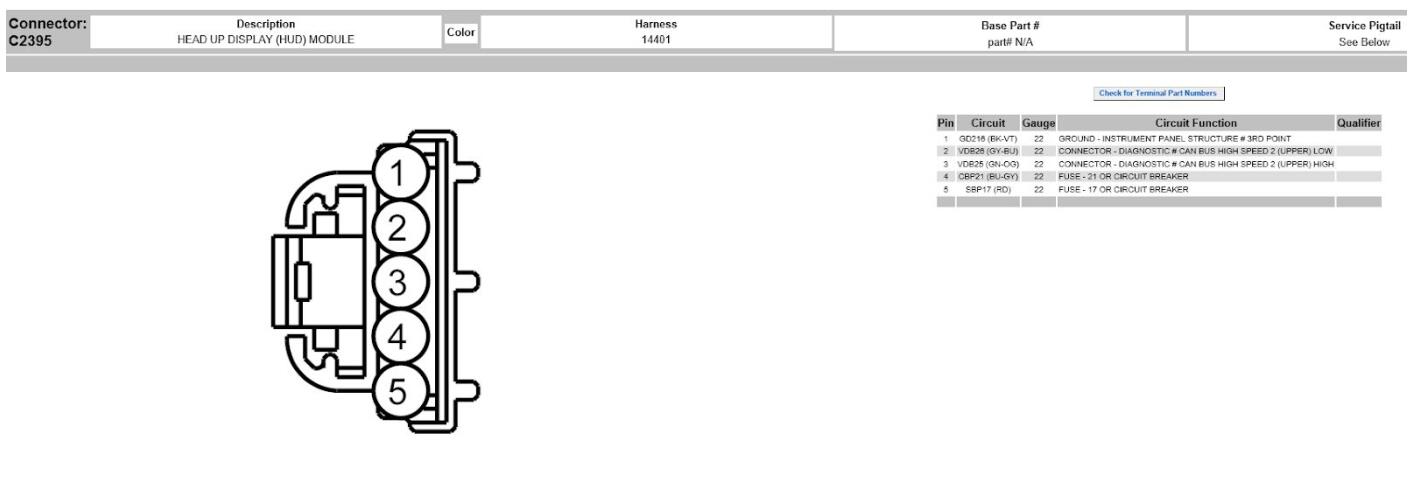
The C2395 HUD Module connector 6U2Z-14S411-SB (Motorcraft Part # WPT-983) has 5 wires (dots identify the terminal #s)
1.Wire # 1 goes to Ground.
2.Wire # 2** goes to C210 Inline Connector (behind glove box) Pin # 9 (VDB26 / GY-BU)
3.Wire # 3**goes to C210 Inline Connector (behind glove box) Pin # 10 (VDB25 / GN-OG)
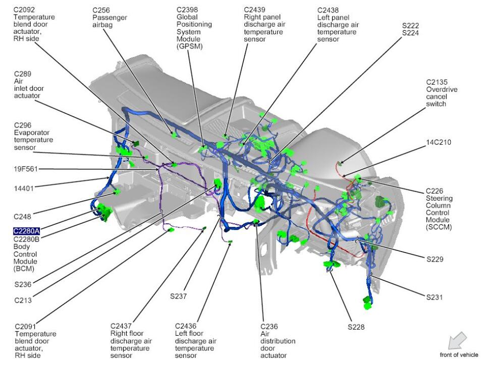
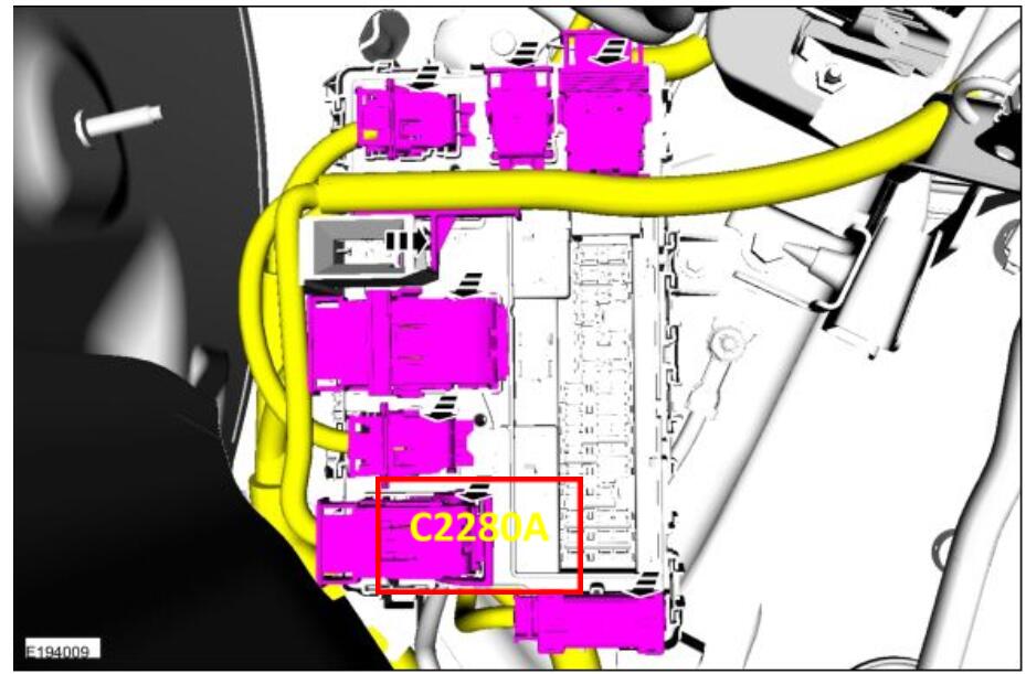
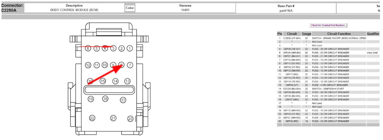
4.Wire # 4 goes to BCM Connector C2280A (Connector in passenger foot well) Pin # 6 (CBP21 /BU-GY)
5. Wire # 5 goes to BCM Connector C2280A (Connector in passenger foot well) Pin # 11
**Note: wires # 2 & 3 should be a twisted pair
- Using (5) different color wires, add 10 feet of 20 gauge wire to each of the (5) terminals of theWPT-983 HUD Module connector. Tape the additional wiring with tesa tape or equivalent. Routethe new harness behind the center console to the area behind the glove box.
● Connect wire # 1 of WPT-983 to a suitable ground.
● Behind glove box, connect wire # 2 of WPT-983 to C210 Inline Connector wire # 9 (VDB26 /GY-BU) and wire # 3 of WPT-983 to C210 Inline Connector wire # 10 (VDB25 / GN-OG).
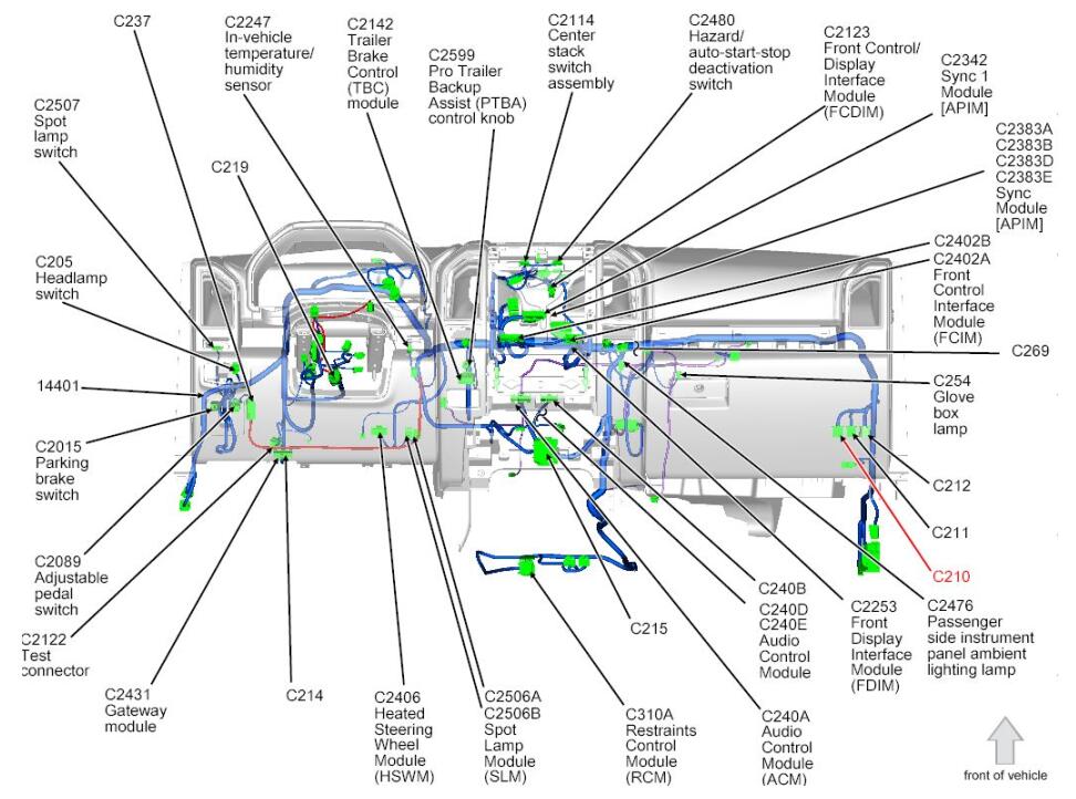
At the BCM (Passenger foot well compartment) connect wire # 4 of WPT-983 to C2280A BCM
connecter wire #6 (CBP21 / BU-GY). Using DU2Z-14474-DA (Motorcraft Part # WT-1003) pigtail,
add wire # 5 of WPT-983 to C2280A BCM connector at location # 11.
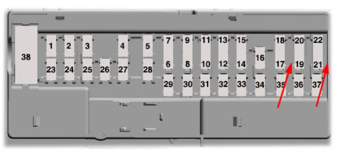
Confirm the presence of 5 amp fuses at location # 17 & 21 of the BCM
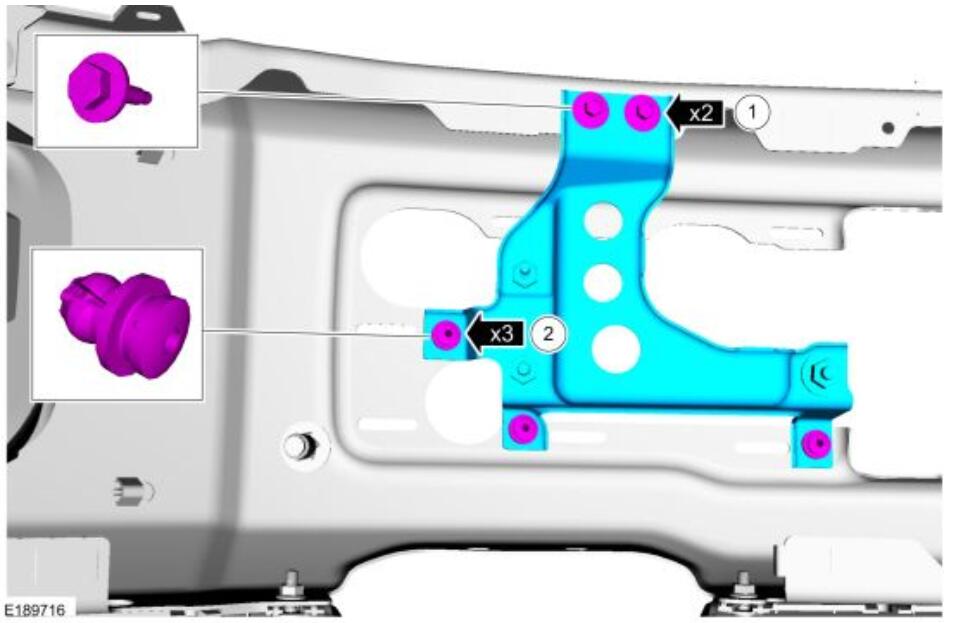
Cruise Control Module (C-CM) Bracket Mounting:
Module Programming Using FORScan:
Preparations:
FORScan Android/iOS/Window Free Download
How to Install & Configure FORScan for OHP ELMconfig
How to Use FORScan to Backup Module Data File
OBDLink MX Bluetooth or OHP Ford ELMconfig USB
● IPC:
o 720-01-01 xFxx xxxx xxxx – CC Options Present
o 720-01-02 xxxx 5xxx – Collision Warn Sensitivity Pres
o 720-04-01 Exxx xxxx xxxx – Collision Warn On/Off Pres
●SCCM:
o 724-03-01 x2xx xxxx xx – ACC left hand steering wheel button configuration
● BCM:
o 726-13-01 xxxC 4xxx xxxx – Adaptive Cruise Control & Collision Mitigation by Braking
● ABS :
o 760-03-01 7xxx xx
● C-CM:
o 764-01-01 0816 0101 8D
o VIN Specific
o VIN Specific
o VIN Specific
o VIN Specific