This installation instructions are focus on how to retrofit BMW X3 E83 navigation system on-board monitor.It is only valid for cars without SA358(climate comfort windscreen).And the installation time is 5.5 hours,but this may vary depending on the condition of the ar and the equipment in it.
Retrofit kit No. 65 90 0 306 977
2024.08 BMW Rheingold ISTA+ 4.48.40 4.23.14 ISTA-P 3.71 Free Download
Important information
These installation instructions are primarily designed for use within the BMW dealership organisation and by authorised BMW service companies.
In any event the target group for these installation instructions is specialist personnel trained on BMW cars with the appropriate specialist knowledge.
All work must be completed using the latest BMW repair manuals, circuit diagrams, servicing manuals and work instructions in a rational order using the prescribed tools (special tools) and observing current health and safety regulations.
To avoid unnecessary extra work and/or costs, if any installation or function problems occur,
after a brief troubleshooting session (approx. 0.5 hours), an inquiry is to be sent straight away to
the technical parts support via the Aftersales Assistance Portal (ASAP), quoting the chassis
number, the part number of the retrofit kit and a precise description of the problem.
Ensure that the cables/lines are not kinked or damaged as you install them in the car. The costs incurred as a result of this will not be reimbursed by BMW AG.
Additional cables/lines that you install must be secured with cable ties.
If the specified PIN chambers are occupied, bridges, double crimps or twin-lead terminals must be used.
All the figures show LHD cars, proceed in exactly the same way on RHD cars.
After the installation work the retrofit kit must be programmed / coded using DISPlus or GT-1 via the CIP path.
Installation information
The wiring harness between the CD changer and CID control must be retrofitted in cars with a CD
changer (SA 672) and a Professional hi-fi system (SA 677).
Ordering instructions
The CID control is not included in the retrofit kit and must be ordered separately (see EPC for part
number and documentation).
The wiring harness between the CD changer and CID control is not included in the retrofit kit and must
be ordered separately (see EPC for part number and documentation).
List of special equipment
The following special equipment must be taken into consideration when installing the upgrade kit:
SA 672 CD changer
SA 692 CD changer preparation
Special tools required
Release hook (64 1 020)
Parts list:
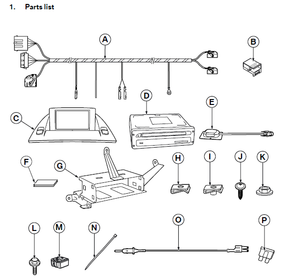
A Wiring harness I Speed nut M6 (2x)
B Socket casing J Philips screw 4.2 x 13 mm (2x)
C Central Information Display (CID) K Hexagonal nut M6
D Navigation computer L Hexagonal screw M6 x 16 mm (2x)
E GPS aerial M Insulation-piercing connector (2x)
F Velcro tape N Cable tie (15x)
G Navigation computer holder O Power supply cable (for cars without SA 672
or SA 692 only)
H Speed nut (2x) P Fusible insert, 10 A (for cars without SA 672
or SA 692 only)
Preparations
| TIS No. | |
| Conduct a brief test | — |
| Disconnect the negative pole of the battery | 12 00 … |
| The following components must be removed first of all | |
| Instrument cluster | 62 11 280 |
| Centre fresh air grille | 64 22 162 |
| Oddments box in the instrument panel | 51 45 … |
| Control for the heating/air-conditioning system | 64 11 377 |
| Radio receiver (CID control) | 65 11 080 |
| Glove compartment | — |
| Release the joint connector box behind the glove compartment | — |
| Pedal trim | 51 45 185 |
| Front left door sill strip | 51 47 000 |
| Rear left door sill strip | — |
| B pillar trim, left | 51 43 148 |
| Rear seat cushion | 52 26 005 |
| Backrest side section on the rear seat backrest | 52 26 008 |
| Flap in boot trim, left | 51 47 172 |
| Boot trim on the left | — |
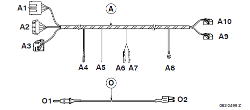
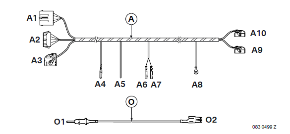
Connection diagram
| Item | Description | Signal | Cable colour / Cross-section |
Connection location in the car | Abbreviation / Slot |
| A | Wiring harness | — | — | — | — |
| A1 | SW 8-pin plug casing | — | — | Plug X322 | X322 |
| A2 | 8-pin socket casing SW | — | — | Plug X322 | X322 |
| A3 | 18-pin socket casing WS | — | — | CID C | X18802 |
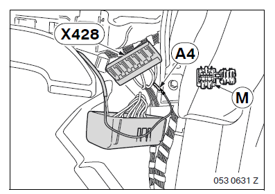
| A4 | Joint connector contact | Reversing signal |
BL/GE 0.75 mm2 |
Joint connector behind the glove compartment |
X428 |
| A5 | Open cable | TAA | SW/WS 0.35 mm2 |
To the GE/GN cable from plug X11175 from the instrument cluster using an insulationpiercing connector M |
X11175 PIN 6 |
| A6 | Socket contact | NAV NF+ | GE/RT 0.5 mm2 |
CID control | X13649 PIN 5 |
| A7 | Socket contact | NAV NF- | GE/BR 0.5 mm2 |
CID control | X13649 PIN 11 |
| A8 | Cable eyelet | Terminal 31 |
BR | Earth post in the boot on the left | X13200 |
| A9 | 18-pin socket casing VI | — | — | Navigation computer D | X1312 |
| A10 | 18-pin BL socket casing | — | — | Navigation computer D | X1313 |
| O | Power supply cable | — | — | For cars without SA 672 or SA 692 only | — |
| O1 | Plug contact | Terminal 30 |
RT/GE 1.5 mm2 |
Plug X322 | X322 PIN 3 |
| O2 | Double flat spring contact | Terminal 30 |
RT/GE 1.5 mm2 |
Fuse holder behind the glove compartment | X10015 PIN 5 |
Installation and cabling diagram
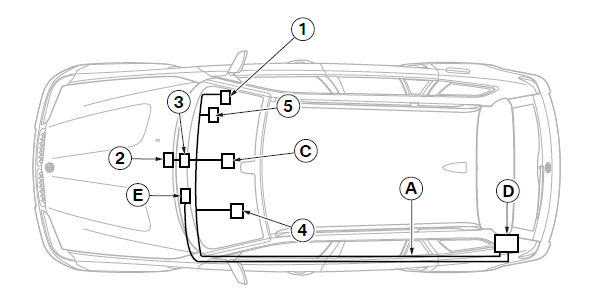
A Wiring harness
C CID
D Navigation computer
E GPS aerial
1 Joint connector X428
2 Plug X322
3 CID control X13649
4 Plug X11175
5 Fuse holder behind the glove compartment
To install the GPS aerial
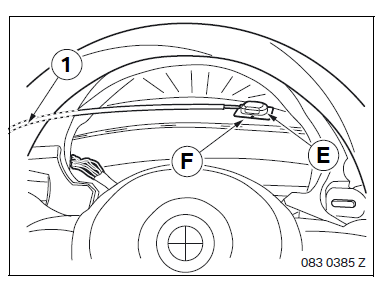
Clean the support areas of the GPS aerial E and the ventilation shaft with a conventional cleaning product.
Secure the GPS aerial E to the ventilation shaft using Velcro tape F.
Route the aerial cable (1) for the GPS aerial E along the standard wiring harness into the boot on the left.
To install and connect the wiring harness
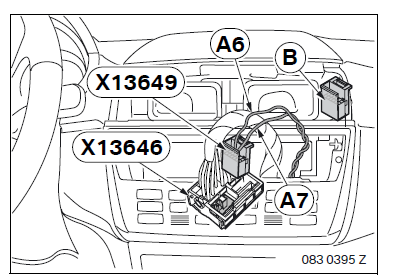
Disconnect plug X13649 from radio plug X13646 and connect branches A6 and A7 as
follows:
– Branch A6, GE/RT cable to PIN 5
– Branch A7, GE/BR cable, to PIN 11
If there is no plug X13649, use the socket casing B.
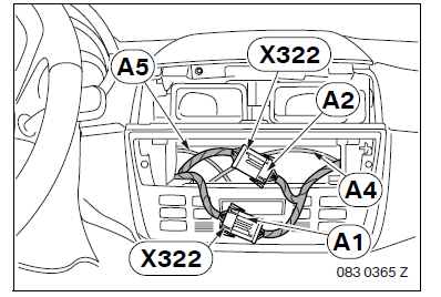
Disconnect plug X322 and connect branches A1 and A2 in parallel between plug X322.
Route branch A5 to the instrument cluster.
Route branch A4 behind the glove compartment.
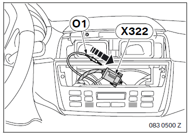
Cars without SA 672 or SA 692 only
Connect branch O1 to PIN 3 of plug casing X322.
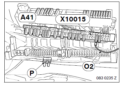
Route branch O2 to the fuse holder and connect it to plug X10015 PIN 5.
Insert fusible insert P into slot 42.
To install and connect the wiring harness
All cars
Connect branch A4 to joint connector X428, BL/GE cable.
If joint connector X428 is fully occupied,connect branch A4 using an insulationpiercing connector M.
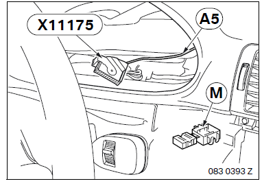
Connect branch A5 to the GE/GN cable from PIN 6 of plug X11175 using an insulating-piercing connector M.
Route branches A8, A9 and A10 along the standard wiring harness into the boot on the left.
To install and connect the CID control
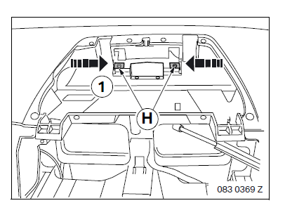
Place speed nuts H on the function holder (1).
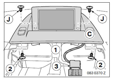
Secure the CID C to the function holder (1) using Philips screws J and the existing screws (2).
Route the connection plug (3) to the radio slot.
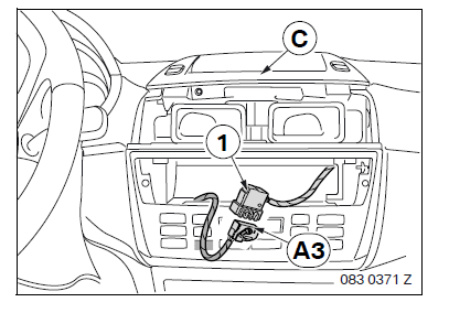
Connect branch A3 to the connection plug (1) on the CID C.
Secure the plug connector in a suitable position using a cable tie N.
To install and connect the navigation computer
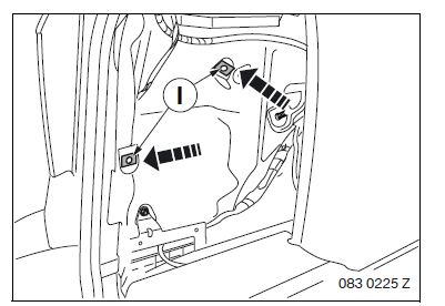
Push speed nuts I on to the wheel arch plate on the left-hand side of the boot.
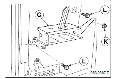
Secure the navigation computer holder G in the boot using hexagonal screws L and hexagonal nuts K .
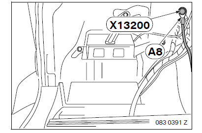
Secure branch A8 to the earth connector X13200.
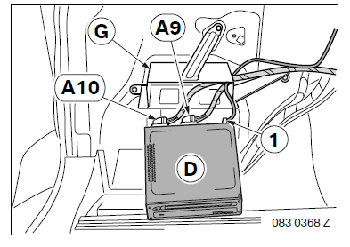
Connect branches A9, A10 and the aerial plug (1) for the GPS aerial E to the navigation computer D.
Slide the navigation computer D into the navigation computer holder G.
Concluding work and coding
Do not insert the software CD into the navigation computer until prompted to do so during the
coding procedure (risk of damaging the navigation computer).
– Connect the battery
– Encode the retrofit using DISPlus or GT-1 via path CIP
– In cars with a DSP amplifier, re-code this as well
– Conduct a brief test
– Conduct a function test
– Re-assemble the car
Circuit diagram
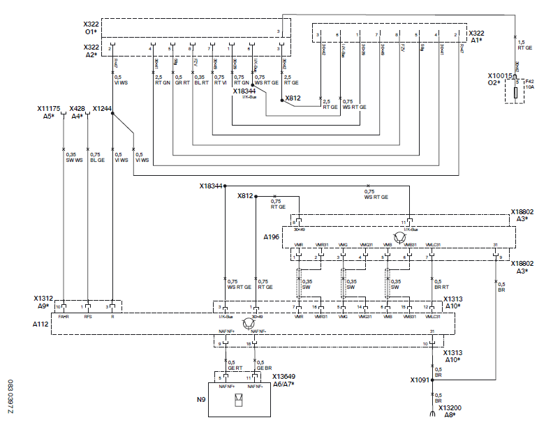
A112 Navigation computer
A196 CID
N9 Radio
X322 SW 8-pin plug, A1/A2*, O1*
X428 Joint connector, reversing light, A4*
X812 Terminal 30 connector
X1091 Terminal 31 connector
X1244 Terminal R connector
X1312 18-pin socket casing VI, A9*
X1313 18-pin BL socket casing, A10*
X10015 Socket casing SW, O2*
X11175 26-pin socket casing SW, A5*
X13200 Terminal 31 cable eyelet, A8*
X13649 12-pin socket casing SW, A6/A7*
X18344 I/K BUS connector
X18802 18-pin socket casing WS, A3*
All the designations marked with an asterisk (*) apply only to these installation instructions or this circuit diagram.
Cable colours
BL Blue
BR Brown
GE Yellow
GN Green
GR Grey
RT Red
SW Black
VI Violet
WS White