This installation instructions show a guide on how to perform BMW X5 and X6 (E70 and E71) round vision retrofit guide.These installation instructions only apply to cars with retrofitted BMW ACM accessories menu.
And for more BMW retrofit,you can check here:BMW Retrofit Projects
2024.08 BMW Rheingold ISTA+ 4.48.40 4.23.14 ISTA-P 3.71 Free Download
On cars without ACM, the installation instructions 01 29 0 417 584 (Rear View) and/or 01 29 0 418 007 (Side View) must be used.
Retrofit kit no.:
66 21 0 442 573 Round Vision Retrofit with 2 cameras
66 21 0 445 720 Round Vision retrofit kit with 4 cameras
Installation time
The installation time is approx. 2.5 to 3.0 hours. This may vary depending on the condition of the car and the equipment in it.
Important information
These installation instructions are primarily designed for use within the BMW dealership organisation and by authorised BMW service companies.
In any event, the target group for these installation instructions is specialist personnel trained on BMW cars with the appropriate specialist knowledge.
All work must be completed using the latest BMW repair manuals, circuit diagrams, servicing manuals and work instructions, in a rational order, using the prescribed tools (special tools) and observing current health and safety regulations.
If you experience installation or function problems, restrict troubleshooting to approx. 0.5 hours for mechanical work and 1.0 hour for electrical work.
In order to reduce costs and avoid any additional expense, send a query immediately to the Technical Parts Support via the Aftersales Assistance Portal (ASAP).
Specify the following information:
– Chassis number
– Part number of the retrofit kit
– A precise description of the problem
– Work steps already carried out
Do not archive the hard copy of these installation instructions since daily updates are made by ASAP!
Pictograms
Denotes instructions that draw your attention to dangers.
Installation information
Due to the large number of bumper trims, the installation of the Side View cannot be shown in detail for every equipment variant. The installation work is to be carried out in the same way.
Ensure that the cables and/or lines are not kinked or damaged as you install them in the car. Costs incurred as a result of this will not be reimbursed by BMW AG.
Additional cables/lines that you install must be secured with cable ties.
If the specified PIN chambers are occupied, bridges, double crimps or twin-lead terminals must be used.
All pictures show LHD cars; proceed accordingly on RHD cars.
In most cases, after installation of the retrofit, repairs or a software update of the car, an image
misalignment appears on the Control Display. To correct the image misalignment, the ACM Unit must be initialised.
The initialisation is to be carried out as detailed in the ACM installation instructions 01 29 0 420 167.
Ordering instructions
The rear view Y is not included in the Round Vision retrofit kit with 2 cameras and must be ordered separately (see EPC for part number and further details).
Special tools required
00 9 310, installation wedges
Table of contents
4.Installation and cabling diagram
5.Installing and connecting Side View
6.Installing and connecting rear view
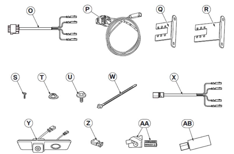
Legend
O Side view wiring harness
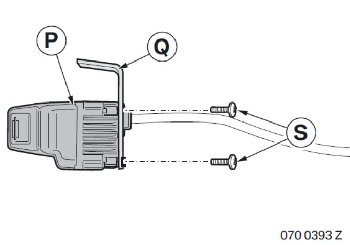
P Side view
Q Holder
R Alternative holder
S Philips screw M2.5 x 5 mm (4x)
T Hexagonal nut with washer M5 (2x)
U Hexagonal screw with washer M5 x 14 mm (2x)
W Cable tie (30x)
X Rear view wiring harness
Y Rear View (not included in the Round Vision retrofit kit with 2 cameras)
Z 2-pin GN plug casing (not included in the Round Vision retrofit kit with 2 cameras)
AA 18-pin socket casing, SW
AB Switching regulator
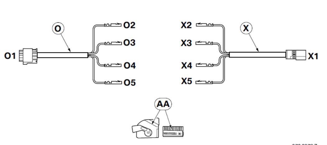
4.Installation and cabling diagram
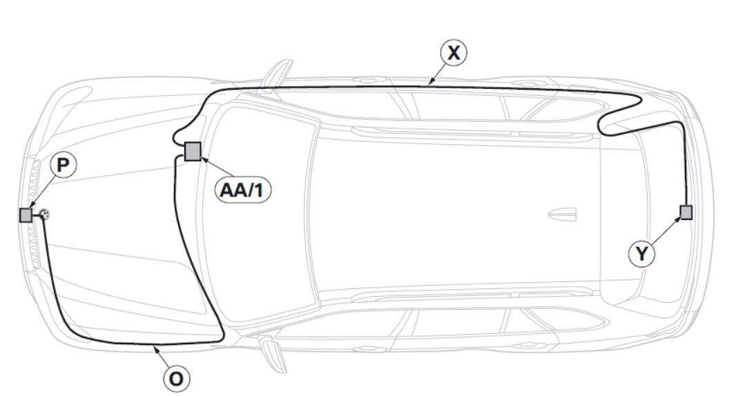
Legend
O Side view wiring harness
P Side view
X Rear view wiring harness
Y Rear view
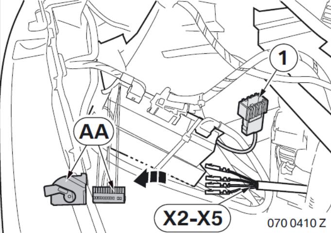
AA 18-pin socket casing, SW
1 Black 18-pin plug casing of the ACM retrofit cable
5.Installing and connecting Side View
Secure side view P to the holder Q using Philips screws S.
Side View P must not project beyond the outline of the car (1), otherwise the homologation for the car will be invalid.
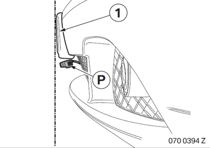
Guide the camera cable (3) through the upper central section of the grille (4), if necessary sawing out one bar of the grille (4).
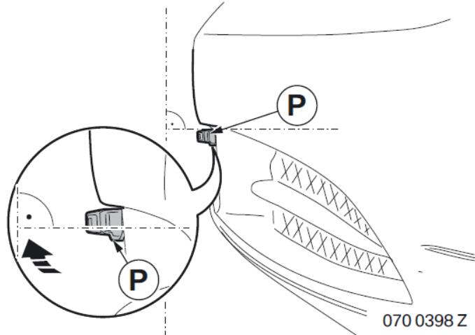
Position side view P in the centre on the underside of the bumper trim (1).
Mark the positions of the holes (2).
Drill through the bumper trim (1) with a 5.5 mm twist drill.
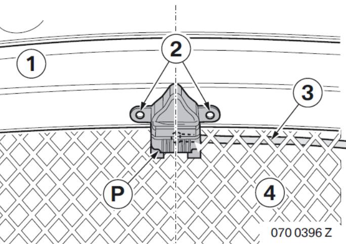
Use hexagonal screws U and hexagonal nuts T to secure side view P on the bumper trim (1).
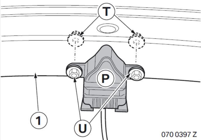
Align Side View P horizontally to the cars axis by carefully bending the holder.
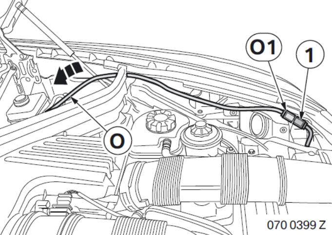
To prevent picture problems, do not connect and secure branch O1 (WS 4-pin socket casing) in the immediate vicinity of the headlight.
Route the camera cable behind the left headlight.
Connect the plug (1) on the camera cable to branch O1.
Install the bumper trim.
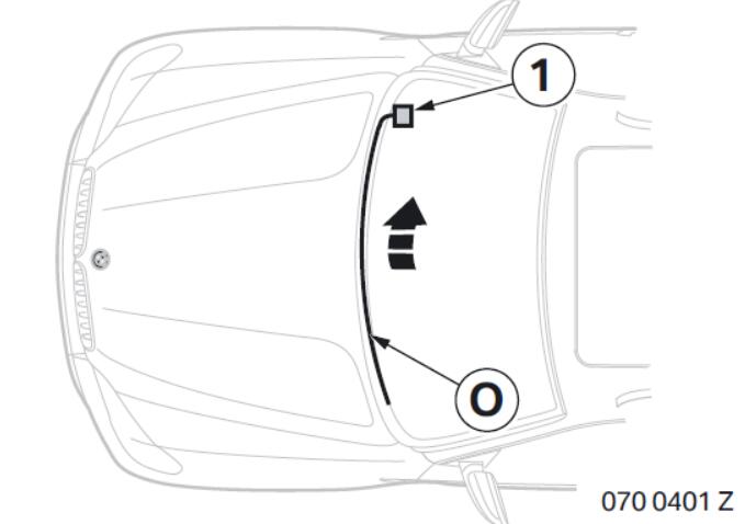
Route the Side View cable harness O to the brake servo unit.
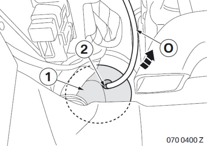
To avoid damaging the reverse brake booster, carefully drill through grommet (1).
Drill through the grommet (1) in the marked area (2) using a 15mm step drill bit.
Route side view wiring harness O through the grommet (1)into the footwell.
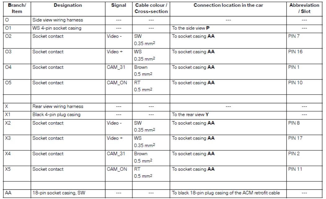
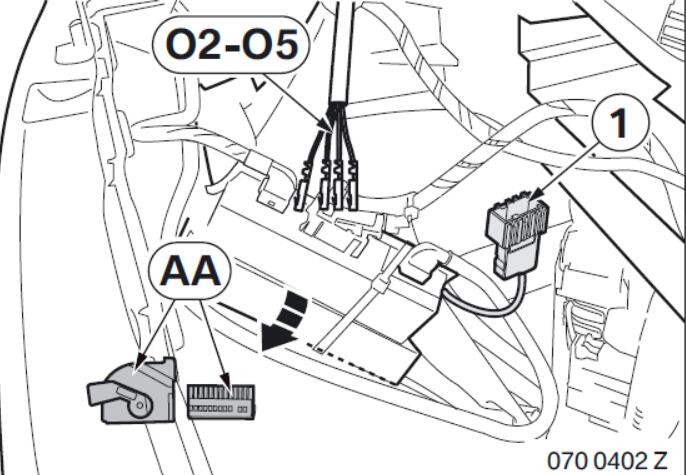
Route side view cable kit O along the standard wiring harness to branch (1), black 18-pin socket casing, from retrofit cable ACM.
Connect branches O2–O5 as follows to socket
casing AA (black 18-pin).
– Branch )2, black cable, to PIN 7
– Branch O3, white cable, to PIN 16
– Branch O4, brown cable, to PIN 1
– Branch O5, red cable, to PIN 10
Keep pin casing (1) of the ACM retrofit cable, black 18-pin for further connection.
6.Installing and connecting rear view
Plug casing Z (green 2-pin) is attached to the connection cable of the button (3).
Disconnect the cable (2) of the button (3) from the existing plug (1) and connect to plug casing Z.
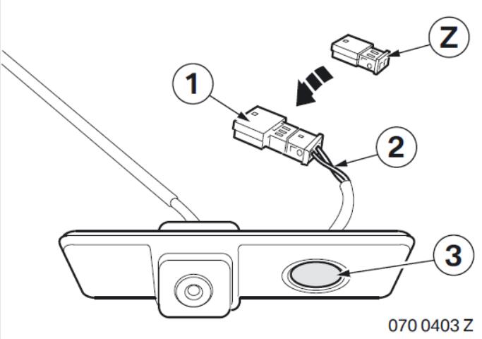
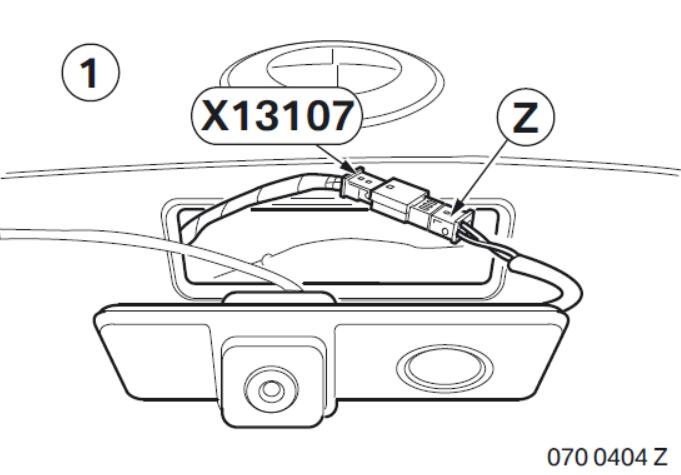
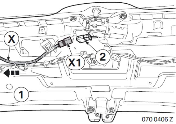
Connect plug casing Z on socket casing X13107 (2-pin SW) of the boot lid (1).
Route the connection plug (2) of the rear view into the tailgate (1) to the wiper motor.
Clip rear view Y into the tailgate (1).
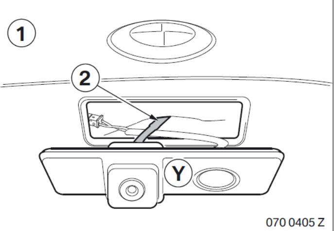
Connect the connection plug (2) of the rear view on branch X1 (black 4-pin plug casing).
Route rear view wiring harness X along the standard wiring harness on the right-hand side of the boot lid (1).
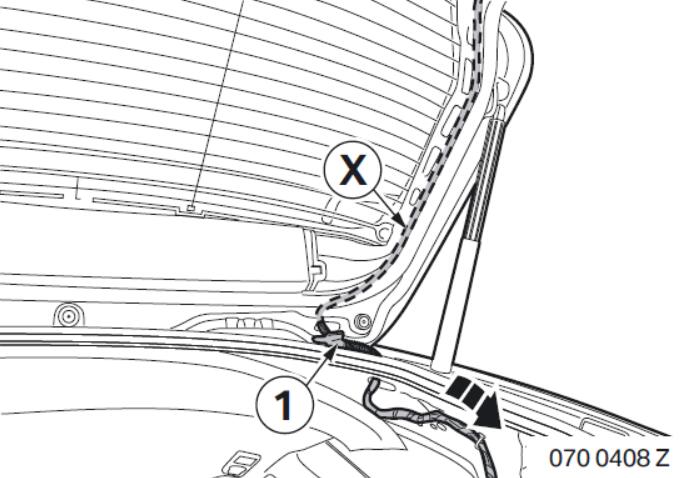
Route rear view wiring harness X along the standard wiring harness through the grommet (1) into the bootspace.
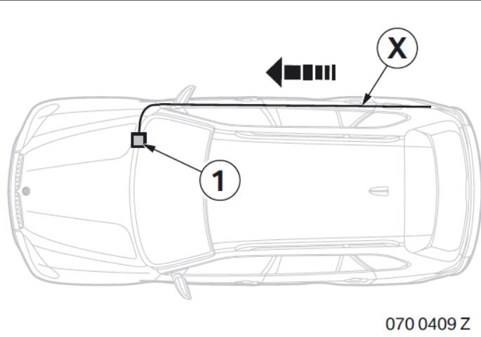
Route rear view cable kit X along the standard wiring harness to branch (1), black 18-pin socket casing, from retrofit cable ACM.
Connect branches X2–X5 as follows to socket casing AA (black 18-pin):
– Branch X2, black cable, to PIN 8
– Branch X3, white cable, to PIN 17
– Branch X4, brown cable, to PIN 2
– Branch X5, red cable, to PIN 11
Connect socket casing AA to pin casing (1) of the ACM retrofit cable, black 18-pin.
Concluding work and coding
This retrofit system does not require coding.
– Connect the battery
– Conduct a brief test
In most cases, after installation of the retrofit, repairs or a software update of the car, an image
misalignment appears on the Control Display. To correct the image misalignment, the ACM Unit must be initialised.
The initialisation is to be carried out as detailed in the ACM installation instructions 01 29 0 420 167.
– Conduct a function test
– Re-assemble the car
Legend
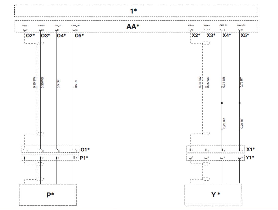
All the designations marked with an asterisk (*) apply only to these installation instructions or this circuit diagram.
O1* WS 4-pin socket casing
O2* Socket contact
O3* Socket contact
O4* Socket contact
O5* Socket contact
P* Side view
P1* 4-pin WS plug casing
X1* Black 4-pin plug casing
X2* Socket contact
X3* Socket contact
X4* Socket contact
X5* Socket contact
Y* Rear view
Y1* 4-pin socket casing, SW
AA* 18-pin socket casing, SW
1* Black 18-pin plug casing on ACM retrofit cable
Cable colours
Brown Brown
GN Green
RT Red
SW Black
WS White