This is an instruction on how to install piston for MTU 12-16V 4000 engine with conrod in assembly dolly.
Related Contents:
2022 MTU DiaSys 2.74 2.72 Engine Diagnostic Software Free Download
MTU Diagnostic Tool USB-to-CAN with MTU Diasys 2.73
Procedures:
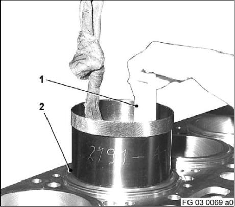
Installing piston with conrod in assembly dolly
Note: Always make sure that all components are perfectly clean.
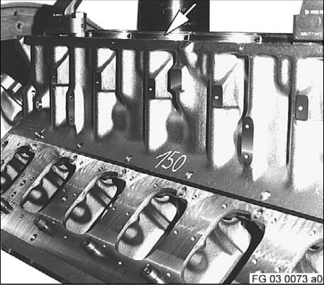
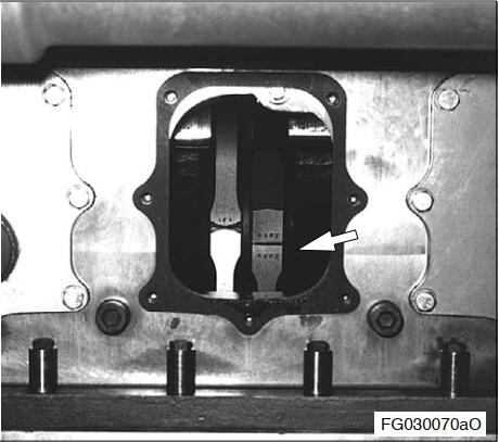
Rotate crankcase in assembly dolly until cylinder liner (arrow) is vertical.
Note: Crankshaft must be turned only with flywheel installed or when axially located
Turn crankpin of crankshaft of piston to be installed and connecting rod to assembly position.
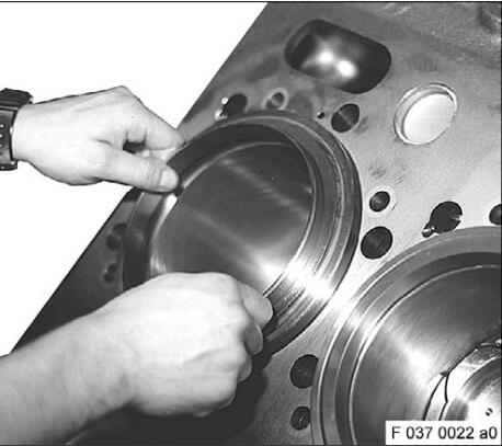
Wipe crankpin and running surface of cylinder liner and spray with engine oil.
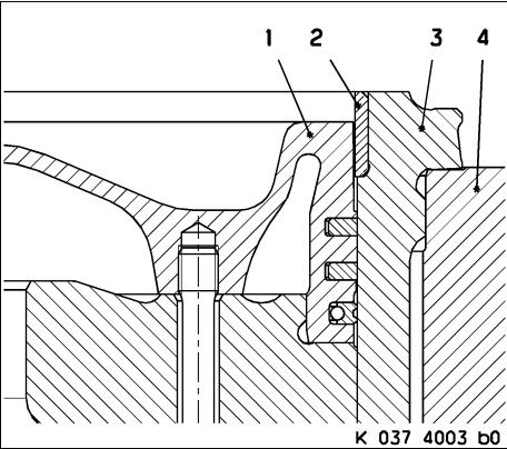
Cylinder liner with carbon scraper ring
Running surface of piston crown is machined according to carbon scraper ring.
1 – Piston
2 – Carbon scraper ring
3 – Cylinder liner
4 – Crankcase
Attention: Install piston without carbon scraper ring.
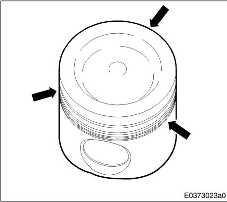
Spray the piston and piston rings with engine oil.
Ensure that piston rings (arrow) are evenly fitted around piston circumference.
Centre rings in grooves.
In particular, the DSF ring with coiled spring expander must be centred carefully in order to avoid damage.
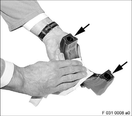
Blow out interfaces (arrows) on connecting rod and conrod cap with compressed air and check that they are clean.
Toothing on mating faces must not be damaged. Replace conrod as necessary.
Wipe bearing shell mating faces on connecting rod and conrod cap.
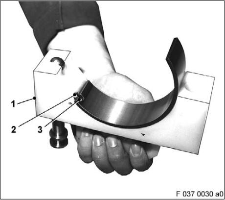
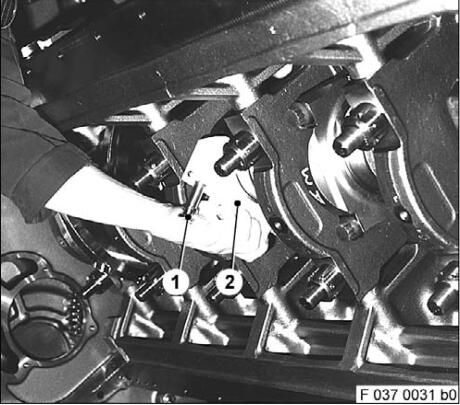
Place conrod bearing “groove” (bottom) in assembly device (1) so that conrod bearing recess (3) engages in locating pin (2).
Coat friction face of bearing shell with engine oil.
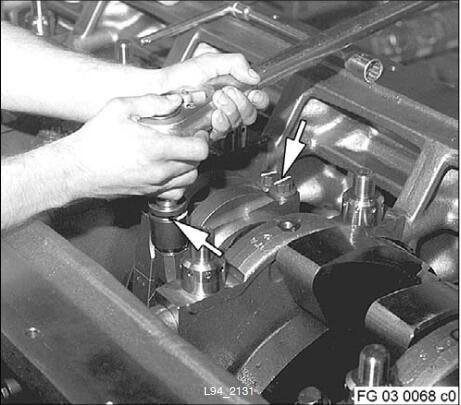
Press assembly device (arrow) with bearing shell half by hand on crankshaft crankpin.
Coat “sputter” (top) running surface of bearing shell with engine oil.
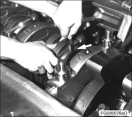
Position second bearing shell half (1) with recess for
locating pin on crankpin (2) so that the two recesses are aligned.
Note: In order to guide the conrod and avoid damage to the oil spray nozzle, piston installation must be carried out by two people.
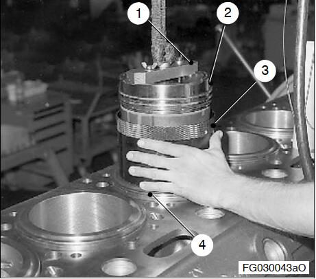
Attach lifting appliance (1) for piston (2).
Lubricate running surface of piston assembly sleeve (3) with oil.
Place piston assembly sleeve on appropriate cylinder liner (4).
Note: For cylinder liner with carbon-deposit scraper ring, use an appropriate assembly sleeve
with collar.
Suspend piston with ropes and pass through assembly sleeve into cylinder liner.
Install piston into cylinder liner so that short arm of conrod points outwards to air intake side.
Gently turn piston when inserting so that the oil spray nozzle is not damaged when the conrod is installed.
If the oil spray nozzle is damaged, remove spray nozzle and replace.
Use mandrel (1) to press piston into cylinder liner (2).
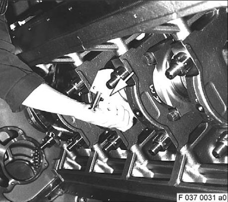
Place conrod on assembly device (2) for conrod bearing.
At same time, position assembly device with guide pin (1).MTU Engine USB to CAN diagnostic adapter
Remove assembly device and press conrod cap by hand onto conrod and position with adjusting mandrel.
Pay attention to fit of locating pin in recess in conrod cap.
Measure shaft length of conrod screws; for max. shaft length.
Coat threads and screw head seating surfaces (arrows) with engine oil.
Carefully insert conrod screw into bearing cap bore by hand to first contact with thread flanks, then turn first three rotations without a tool.
Install conrod cap screws (arrow) until screw heads make contact and use socket wrench to tighten by hand.
Conrod and conrod cap serrations must be closed.
First tighten conrod cap screw at short conrod arm and then on long conrod arm to specified torque.
Checking axial clearance of connecting rod.
Mark screw heads (arrows).
Tighten conrod screws through specified angle of further rotation.
Check checking torque in tightening direction as per tightening specifications.
Again check axial clearance.
Note: Remove lifting device and assembly sleeve for piston with connecting rod.
Bar crankshaft and ensure that there is ease of movement between oil spray nozzle, piston and conrod.
Installing carbon scraper ring
Check axial clearance of connecting rod
Check distance between crankshaft web and conrod or between conrod and conrod, pressed towards each other.
The above-stated components must not touch each other.
Use feeler gauge (arrow) to measure ring end clearance, pressing on three levels.
Min. clearance = 0.20 mm
Max. clearance = 0.60 mm
If the specified clearance is exceeded or undershot,adjustment is necessary.
Release conrod cap screws, compensate clearance in axial area and again tighten as per tightening specifications.
Install piston with connecting rod with oil pan installed (via access port)
Apart from the unaltered installation position of the crankcase (engine in normal position), installation of the conrod bearings, conrod caps and conrod screws through the access port (arrow), is in principal the same as for – Installing piston with connecting rod in assembly dolly.
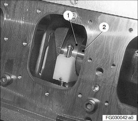
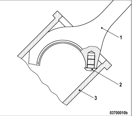
Before installing, mount the sliding block on the connecting rod to be installed, see next illustration.
1 Connecting rod
2 Sliding block
3 Cylinder liner
Inserting carbon scraper ring.
Before installing, spray cylinder liner and carbon scraper ring with engine oil.
Insert carbon scraper ring.
Defining piston TDC
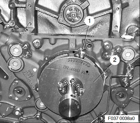
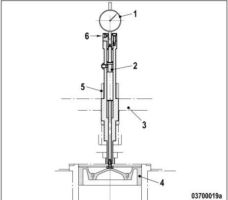
Install pointer (1) on equipment carrier.
Install graduated disc (2) with barring tool on crankshaft, free end.
Install dial gauge (1) under preload in measuring unit (2) and clamp with screw (6).
Install measuring unit in cylinder head (3) and secure with hold-down clamp (5).
Set dial gauge to zero.
Move piston (4) up and down several times until pointer on dial gauge shows its maximum reading.
Set dial gauge to zero and readjust index plate accordingly.
Bar crankshaft in normal direction of rotation to 5° before TDC, read dial gauge and make a note of measured value.
Bar crankshaft past TDC to approx. 10° (to take up bearing play).
Bar crankshaft in direction opposite to normal direction of rotation to 5° after TDC, read dial gauge and make a note of measured value.
Example:
| Piston to 5° before TDC Piston to 5° after TDC |
– 0.36 mm – 0.32 mm |
| –––––––––––––––––––––––––––––––––– | |
| Total values Mean value |
= 0.68 mm = 0.34 mm |
Bar crankshaft to approx. 10° after TDC, then bar in direction opposite to normal direction of rotation until dial gauge reads mean value, i.e. = 0.34 mm.
Set pointer of index plate to 5° after TDC and tighten.
Inspection: Absolute TDC is reached when the dial gauge shows the same values before and after TDC at the same angle. To eliminate bearing clearance,the piston must always move in direction of TDC.
More repair case for MTU engine,please refer to:MTU Engine Trouble Repair