Here is a illustration for how to solve Volvo EC210C LD excavator cooling system exhaust gas leakage.
Related Contents:
2024 Volvo TechTool PTT 2.8.241 APCI 0.7.1.0/2.7.116 All Version Free Download
Volvo PROSIS 2023 2019 2018 Parts Catalog & Repair Manuals Free Download
Volvo Diagnostic Kit (88890300)
Volvo VOCOM 88890300 Diagnostic Kit
Applies to
EC160C L Volvo, EC160C NL Volvo, EC180C L Volvo, EC210B F Volvo, EC210B FX Volvo, EC210B LC Volvo, EC210B LR Volvo, EC210B NC Volvo, EC210B NLC Volvo, EC210B Volvo, EC210C L Volvo, EC210C LD Volvo, EC210C LR Volvo, EC210C N Volvo, EC210C NL Volvo, EC235C LD Volvo, EC235C NL Volvo, EC240B FX Volvo, EC240B LC Volvo, EC240B LR Volvo, EC240B NLC Volvo, EC240C L Volvo, EC240C LR Volvo, EC240C NL Volvo, EC290B FX Volvo, EC290B LC Volvo, EC290B LR Volvo, EC290B NLC Volvo, EC290C L Volvo, EC290C LR Volvo, EC290C NL Volvo, ECR235C L Volvo, ECR305C L Volvo, EW160C Volvo, EW180C Volvo, EW210C Volvo, EW230C Volvo, FC2121C Volvo, FC2421C Volvo, FC2924C Volvo, FC3329C Volvo
This Service Bulletin is to be considered as technical information only and is not subject to any reimbursement programs outside normal warranty.
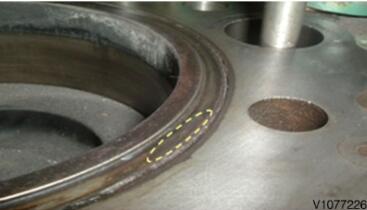
Cylinder liner sealing surface
Cause
The cooling system may become over pressurized due to exhaust gases getting into the coolant passages of the engine block and causing the coolant to come out of the expansion tank in some cases.
This might be because some of the cylinder liner locations, in the cylinder block, have been machined a little deeper than the specification allows for the depth of cylinder liner collar seat
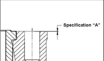
Limit between Cylinder liner sealing surface & cylinder block surface
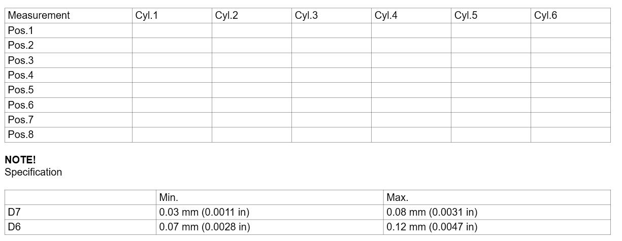
Note! Specification A:
1) D7; Min. 0.03 mm (0.0011 in)/ Max. 0.08 mm (0.0031 in)
2) D6; Min. 0.07 mm (0.0028 in)/ Max. 0.12 mm (0.0047 in)
NOTE!
There are other reasons for exhaust gases in coolant, such as low torque of cylinder head bolts, failed head gasket or cylinder head. It is important to check other reasons of failure before checking on the liner height.
Action
An inspection program, with high frequency measurement, has been introduced to the cylinder block production line in order to provide strict quality control measurement process.
NOTE!
The D6 and D7 engine serial break number, for this improvement, is serial No. 10588594.
As an additional inspection program, 100% measurement of 4 points on all cylinders has been introduced to the cylinder block production line.
NOTE!
The engine serial break numbers, for additional improvement, are
1) D7; 10837245
2) D6; 10873803
Assembly torque process of cylinder head bolts has been updated. In order to improve the capability of the cylinder head bolts, the spindle speed is reduced and also a pause time is introduced in each sequence of the torque processes which is being operated by the robot.
NOTE!
The engine serial break numbers, for another additional improvement, are
1) D7; 11635181
2) D6; 11722178
In case of a field failure,
Contact regional CST technical support via TECHLINE when you have this issue on the machine produced before and after this improvement
First, check and record the toque of cylinder head bolts before removing cylinder head by following work instruction.
Check the cylinder head gasket if there is any defect, such as crack or wearing.
If torque of bolts and head gasket does not show any problem, check the distance between the cylinder liner sealing surface and cylinder block surface by following work instruction.
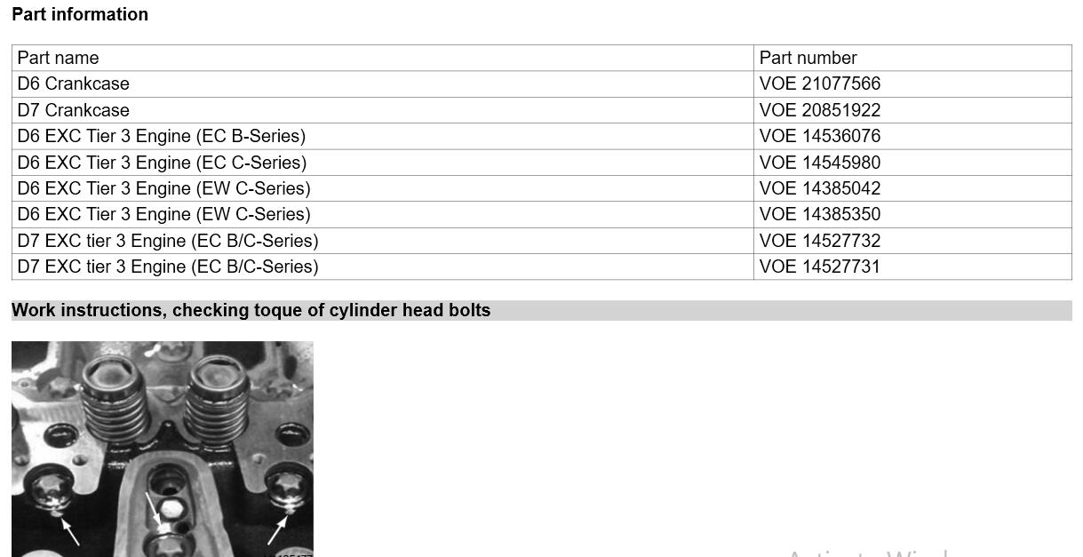
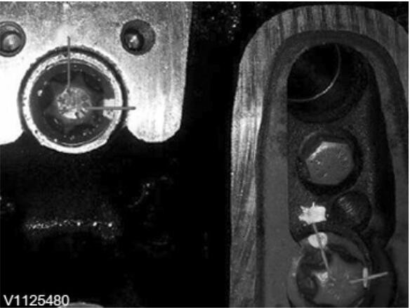
Mark position of screws
1) Mark position of screws before loosening cylinder head bolts.
2) Measure the loosening torque of each bolt. Do not completely remove head bolt while checking.
NOTE!
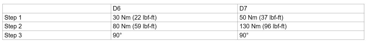
For DE6 engine, start checking from torque 80 Nm (59 lbf ft.) and increase by 5 Nm. For D7E engine, start checking from torque 130 Nm (96 lbf ft.) and increase by 5 Nm.
3) Record the loosening torque value on below table.
4) Retighten the bolt with correct torque without angle 90°. D6E: 30 Nm (1st) + 80 Nm (2nd), D7E: 50 Nm (1st) + 130 Nm (2nd).
5) Mark and note down the new position achieved. Calculate loss angle and record it.
– If the new angle position is located after the earlier angle position in direction of rotation. (A in Fig.4)
e.g.) loss angle = rotation angle tightening (90°) + α
– If the new angle position is located before the earlier angle position in direction of rotation. (B in Fig.4)
e.g.) loss angle = rotation angle tightening (90°) – α
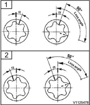
Loss angle calculation
New position after earlier position
New position before earlier position
If the torque values are out of allowed specification (loss angle is permitted to max 60%(54°)), re-torque the head bolt with correct torque with angle and take a picture to see how much it varies with previous position.
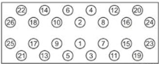
Cylinder head bolts tightening order
NOTE!
When tightening the bolts, follow the tightening order to prevent any damage to cylinder head.
7) If the loss angle is out of allowed value, remove cylinder head and replace the cylinder head gasket with new one.
8) Re-assemble the cylinder head with correct torque.
Checking the position of bolts
NOTE!
Cylinder head bolts can be used max. 3 times with written proof, otherwise renew every time they are loosened.
9) Monitor the machine whether symptom appears again or not.
NOTE!
If the torque of cylinder head bolts meets the specification, visibly check the cylinder head gasket for any crack or damage.
NOTE!
If both the torque of cylinder head bolts and the head gasket do not show any problem, measure the liner height by following instruction.
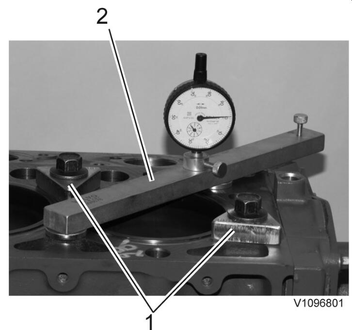
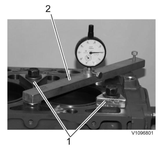
Work instructions, measuring
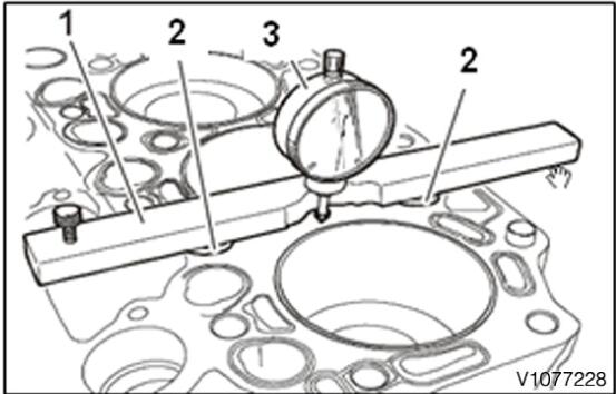
(1) Measuring beam
(2) Shim
(3) Dial gauge
NOTE! Dial gauge reference ; MITUTOYO, No.2046S Use any equivalent type of dial gauge (10mm/ 0.01mm) that can be fixed with 9998678
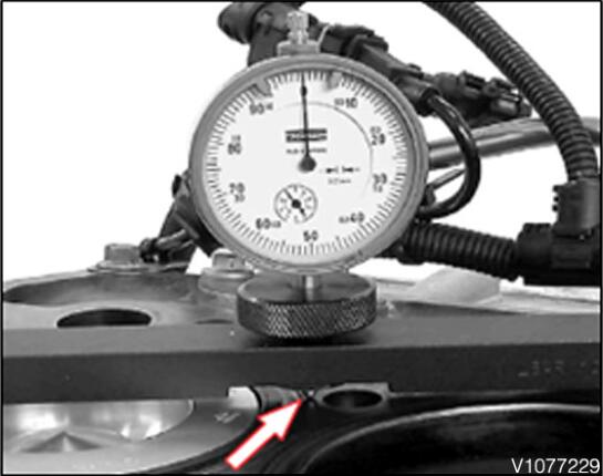
Stylus on the cylinder block sealing surface
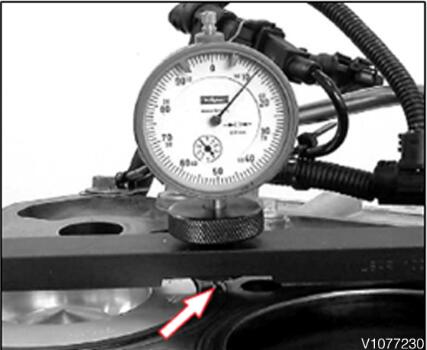
Stylus on the cylinder liner sealing surface
1) Remove the cylinder head and clean the measuring surface thoroughly.
2) Place the shim (2) and measuring beam (1), P/N 9998678 on the sealing surface of the cylinder block.
– Insert a dial gauge (3) into the measuring beam and hold it with a knurled nut. (Refer to Fig. 7)
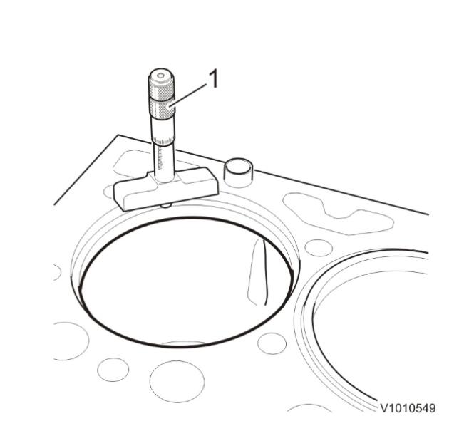
3) Place the stylus of dial gauge onto the cylinder block sealing surface with pre-tension (arrow).
– Adjust the dial gauge to “0”. (Refer to Fig. 8)
4) Move the measuring beam onto the shim so that the stylus is now located on the sealing surface for the cylinder liner (arrow)
– Make a measurement on at least 4 other points for each cylinder liner location, as well as all six cylinder locations
– Fill in the table below
5) Reinstall the cylinder head with new gasket and bolts (Cyl. head bolts may be reused 3 times if there is traceability) if there are no problems with the depth of any of the liner seat machined areas.
Work instructions, milling and adjusting
Milling cylinder liner seat and adjusting cylinder liner height
If the previously described measuring method has shown that the cylinder liner height is outside the tolerance limits, we recommend the following repair actions:
This is done by milling the cylinder liner seat in the engine block together with the use of a spacer ring.
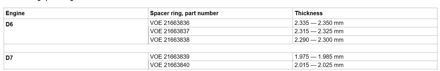
The following spacer ring thicknesses are available from Volvo Parts.
Milling cylinder liner seat and adjusting cylinder liner height.
1.Remove the engine from the machine according to instructions in the service manual.
2.Remove the turbocharger and its oil pipes, and set up the engine in a work stand according to 210, Engine, installing in work stand (in service manual).
3.Remove the valve cover and the hose for the crankcase ventilation, the fuel delivery pipes, fuel control valve, high-pressure pumps, fuel rail (pressure distribution pipe), injectors, IEGR-unit, rocker arm bridges, and the cylinder head. Follow the instructions in 210, Engine, dismantling (in service manual).
4.Install tool 88800129 Press tool, 2 pcs. Tighten the attaching bolts with 40 Nm (29.5 lbf ft). Measure the liner height, the distance between the block face and liner (not the flame edge) to decide if, and how much, the liner position needs to be reworked. Measure in eight places, evenly spaced across the liner edge’s circular periphery. Note the values and calculate an average value.
D6 — Wear limit: 0.07 — 0.12 mm. In our example the average value is: 0.075 mm.
D7 — Wear limit: 0.03 — 0.08 mm. In our example the average value is: 0.03 mm.
88800129 Press tool, 2 pcs.
9998678 Measuring tool
5.Repeat the measurement on the remaining cylinder liners to determine which cylinder liner positions need to be reworked.
6.Depending on which liner position needs to be milled, remove the roller lifters, cable harnesses, belts, charge-air pipe, coolant pump, oil sump, flywheel, timing gear casing, and the starter motor.
NOTE!
Pay attention to what parts are needed when assembling, e.g., new seals, seal rings, pressure pipes for injectors, etc.
7.Remove the piston and connecting rod for the cylinder where the liner position is to be reworked. Also remove the pistons and connecting rods for the adjoining cylinders, otherwise there will not be enough room for the milling tool. See 210, Engine, dismantling (in service manual).
8.Mark the cylinder liner’s position in relation to the block. Remove the cylinder liner. See 210, Engine, dismantling (in service manual).
NOTE!
Adjoining liners must also be removed to make room for the milling tool.
NOTE!
If liner damage is suspected, the above measurement must be repeated with the new liner in place.
9.Clean the liner position thoroughly. Clean the block face from remains of paint and other debris that may give incorrect measuring results.
10.A lot of metal shavings are produced when reworking the liner position, and these will cause major damage if they fall down into the engine. Place protection made of, e.g., foam rubber, up high in the block in the holes for the cylinder liners. Tape the block face thoroughly to prevent metal shavings from falling down into the other cylinders as well as oil and water channels.
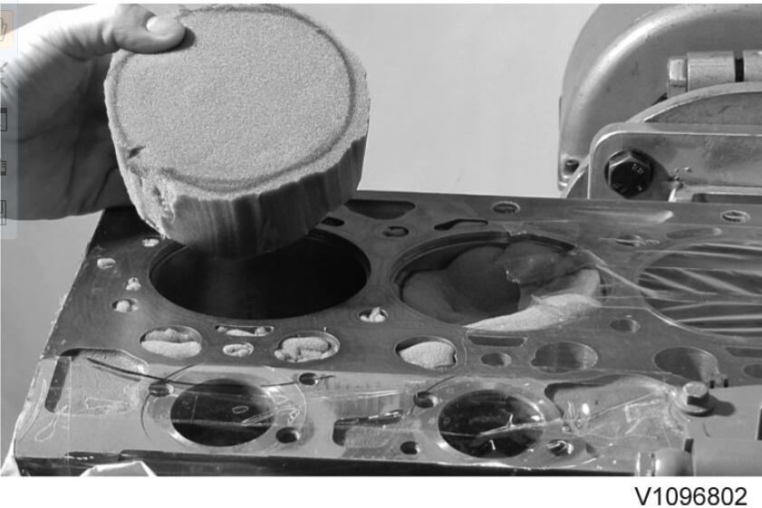
NOTE!
Tape placed where the milling tool is located affects the measuring result. Therefore, plug these channels with foam rubber or similar, or tape tight against the tool.
11.Measure the distance (depth) between the block face and the shelf in the liner position. Measure in eight places evenly spaced across the periphery. Note the values and calculate an average value. In our example the average value is 4.44 mm for D6 and 9.01 mm for D7.
Depth micrometer or similar calibrated tool.
12.Cylinder liner’s height over block face should be (new measurement after reworking and installing adjusting shim, specifications):
D6 – 0.09 — 0.14 mm. Choose 0.14 mm.
D7 – 0.050 — 0.10 mm. Choose 0.10 mm.
— Cylinder liner’s height (measured): 0.075 mm for D6 and 0.030 mm for D7.
— Difference: 0.065 mm for D6 and 0.070 mm for D7.
— Adjusting shims are available in three thicknesses for D6 and two thicknesses for D7:
D6 – 2.290 — 2.300 mm, 2.315 — 2.325 mm, and 2.335 — 2.350 mm. Choose 2.290 mm.
D7 – 1.975 mm and 1.985 mm. Choose 1.975 mm.
— Liner position’s depth: 4.44–0.065=4.375 mm for D6 and 9.01–0.07= 8.94 mm for D7.
— Reworked measurement: 4.375+2.290=6.665 mm for D6 and 8.94+1.975=10.91 mm for D7.
13.Choose a cutting tool of suitable size and check that it is not damaged.
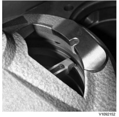
14.Hold up the lock device and install the cutting tool. The toothed edge should face the electromagnet (solenoid) and the centering roller on the side of the spindle which is marked R.
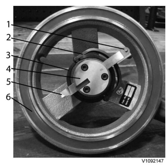
Centering roller
Lock device
Horizontal feed ring
Spindle
Cutting steel
Electromagnet (solenoid)
Vertical feed sleeve
Lock bolt
Scale ring and lock screw (Allen head)
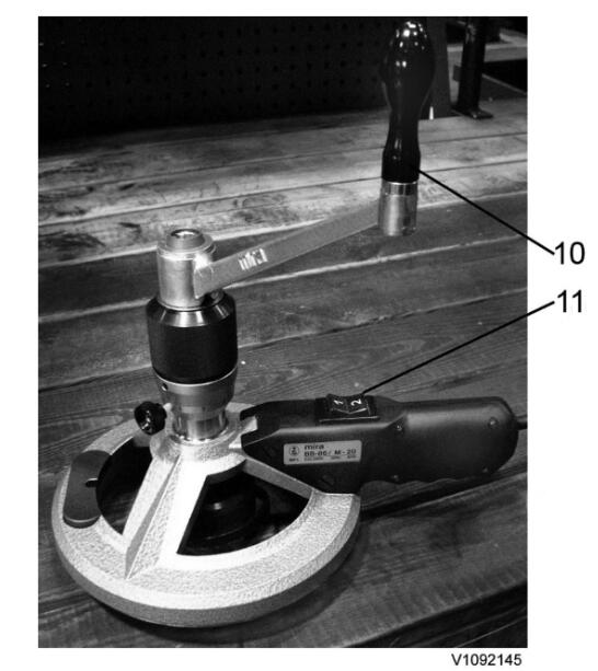
Crank
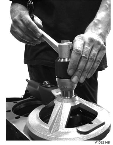
Switch
15.Place the milling tool on the block face so that it is slightly displaced in relation to the middle of the cylinder.
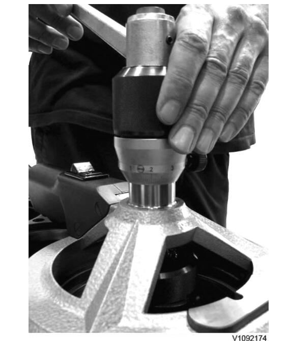
16.Set the switch in position 1 to activate the electromagnet (solenoid).
17.Screw the vertical feed sleeve upwards so that the cutting steel can pass freely over the liner shelf.
18.Press down the lock device and place the centering roller against the liner seat’s wall. Turn the crank clockwise and press in the steel so that the centering roller has contact with the wall where the distance to the wall is the longest.
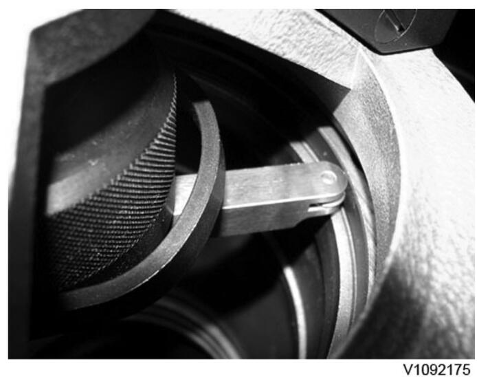
Centering roller
19.Set the switch between position 1 and 2.
20.Center the tool by turning the crank clockwise at the same time as the you hold still the horizontal feed ring.
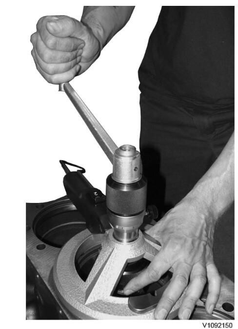
21.The centering roller must be in contact with the liner position’s wall all the time.
If the tool loses contact with the wall:
Turn backwards (counter-clockwise) slightly and repeat the centering procedure.
22.The tool is centered when it stops moving. Set the switch to position 1.
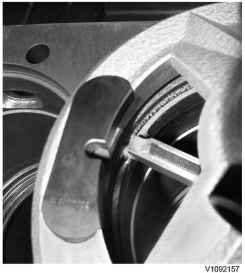
23.Move the cutting steel so that it is positioned over the liner shelf without touching the liner wall.
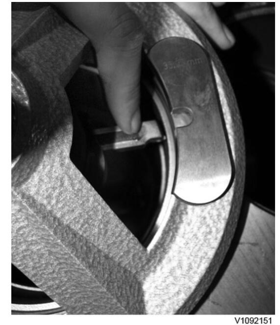
24.Turn the crank and the vertical feed sleeve until the cutting tool comes into contact with the liner shelf.
25.Press down the lock device and move the cutter so that the point ends up just inside the edge on the liner shelf (inner diameter).
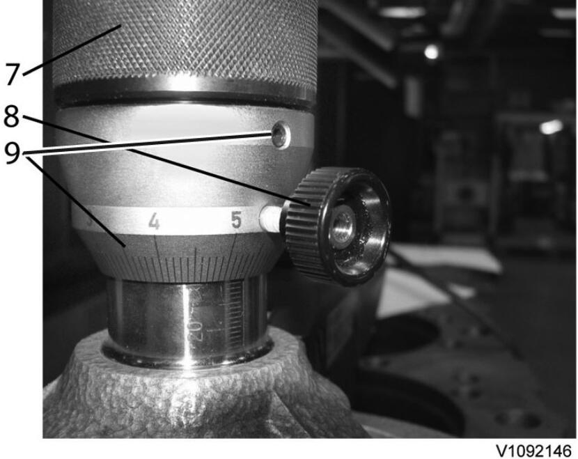
26.Loosen the Allen head screw and reset the tool to zero by turning the scale ring. Lock the scale ring by tightening the Allen head screw.
NOTE!
Use the scale on the scale ring only as an indication of actual reworking depth. Measure the depth with a measuring tool at regular intervals in order to not risk exceeding max. reworking depth. To ensure correct measuring result, remove the milling tool before each measurement. Measuring must take place according to step 34, with cylinder liner and adjusting shim in place.
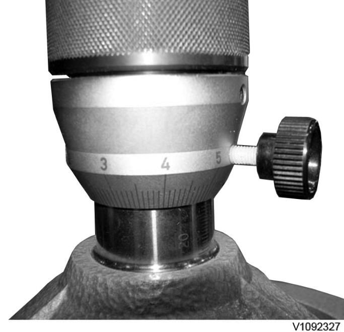
27.Set the scale ring to max. 0.05 mm for the first reworking to check that the cutter mills uniformly around the whole cylinder liner position.
28.Turn the vertical feed sleeve so that the cutter starts to work against the liner shelf.
29.Then rework the cylinder with max. 0.15 mm per reworking.
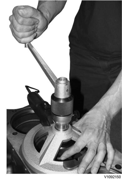
30.Rework the liner shelf by turning the crank clockwise at the same time as the you hold still the horizontal feed ring.
NOTE!
Turn the crank carefully and let the ring slide a little between your fingers during reworking. When the cutting tool approaches the liner shelf’s wall, let the ring slide some more so that you can stop just before the cutting tool reaches the wall.
31.Check with a feeler gauge, vertically down between the steel and the liner wall, so that the cutter horizontally does not pass by the radius between the liner shelf and the liner wall. This is to ensure a satisfactory “pocket” for the adjusting shim.
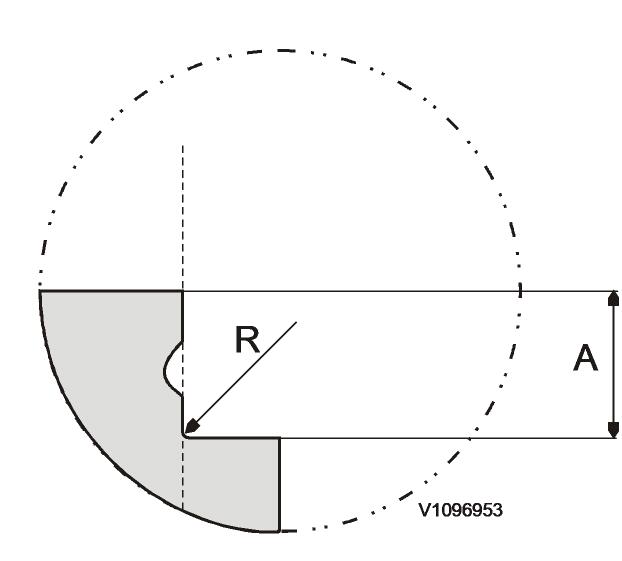
R= 0.3 mm
A= Total liner depth max. 6,745 mm for D6 and 10.91 — 10.94 mm for D7
32.Repeat the procedure but stop reworking when at least 0.05 mm remains to desired depth measurement.
33.Loosen the electromagnet (solenoid) by setting the switch in position 2. Remove the tool.
34.Clean the liner position. Install the adjusting shim and the liner according to marking. Press down the liner with 88800129 Press tool, 2 pcs. Tightening torque: 40 Nm (29.5 lbf ft). Check the liner edge’s height over the block face. Liner edge’s height: 0.09 — 0.14 mm for D6 and 0.050 — 0.10 mm for D7.
88800129 Press tool, 2 pcs.
9998678 Measuring tool
35.Repeat the procedure above until correct distance between liner edge and block face is achieved.
36.Install new seal rings on the cylinder liner.
37.Install the cylinder liner.
38.Assemble the engine according to instructions in 210, Engine, assembling (in service manual).
39.Remove the engine from the work stand and install the turbocharger according to 210, Engine, removing from work stand (in service manual).
40.Install the engine according to instructions in the service manual.
More repair case for Volvo excavator pls refer to:Volvo Excavator Trouble Repair