This instruction show you guide on how to remove PTO,driving end for MTU 12-16 v4000 engine.
Related Contents:
2022 MTU DiaSys 2.74 2.72 Engine Diagnostic Software Free Download
MTU Diagnostic Tool USB-to-CAN with MTU Diasys 2.73
Procedures:
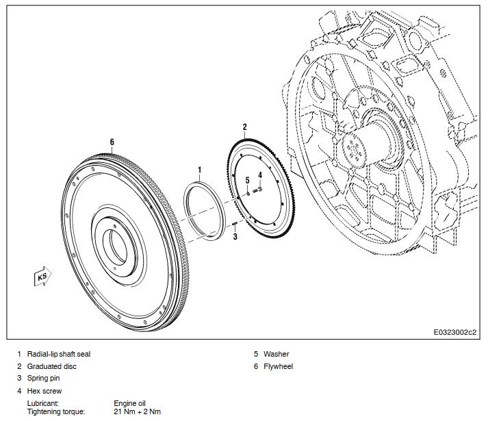
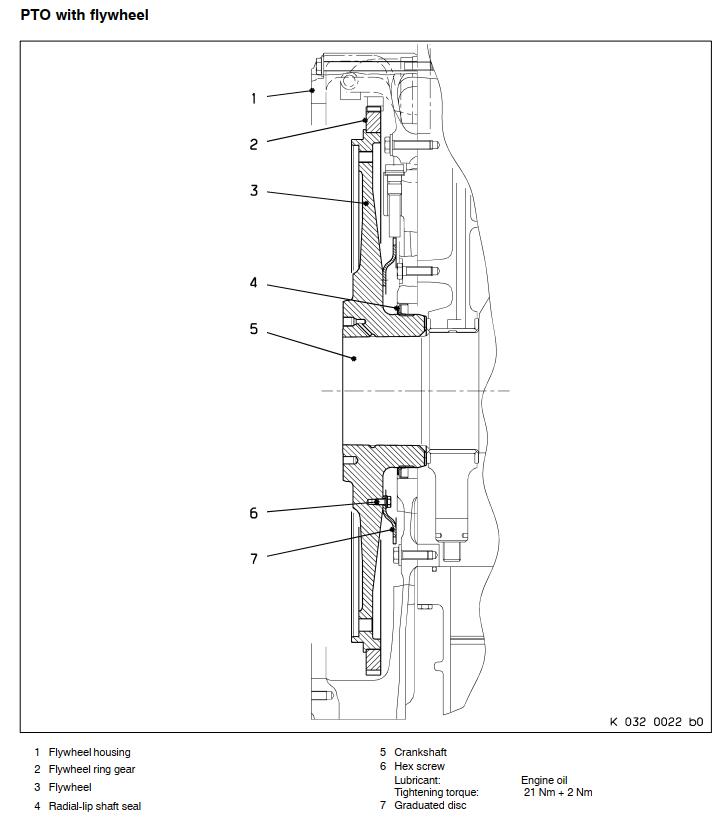
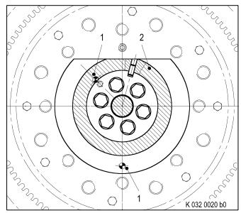
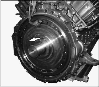
Overview drawing
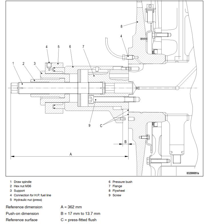
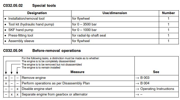
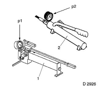
Layout for installation/removal tool for flywheel
Removal:
Install flange with hex screws – see overview
drawing C 032.05 Arrangement, hydraulic installation and removal – on crankshaft journal,
driving end.
Rotate crankshaft so that locating element (1) of pressure bush (2) engages in flywheel.
WARNING
Equipment which is faulty, installed incorrectly or not in accordance with specifications may
become loose or drop off and cause serious injury.
Risk of knocks or crushing!
Liquids emerging under high-pressure can lead to serious injury!
Hydraulic installation/removal must be carried out only by qualified personnel. Only use
specified and tested equipment.
The specified expansion and push-on pressure must not be exceeded.MTU Engine USB to CAN diagnostic adapter
During the installation/removal procedure, make sure that nobody is standing in the danger area. Do not attempt to bend or exert force on high-pressure hoses while they are under pressure.
Always wear protective gloves and protective goggles/safety mask.
For arrangement of installation/removal tool, see overview drawing C 032.05.01.
Screw draw spindle into crankshaft.
For reference dimension (A), see overview drawing
C 032.05.01, Measuring end face of draw spindle to end face of spacer.
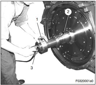
Mount pressure sleeve (2) and hydraulic nut (press) (1) over draw spindle and install nut (3).ÉÉ
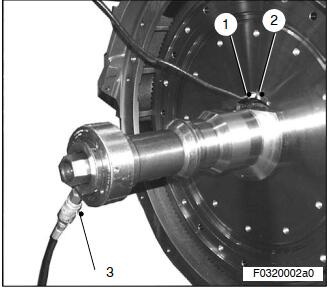
Remove plug from expansion bore in flywheel.
Screw connector (2) into flywheel and connect H.P. line (1).
Connect H.P. line (3) of Lukas hand pump to hydraulic press.
Fully tighten nut then back off nut distance equal to push-on dimension.
Push-on dimension – see overview drawing 032.05.01.
Note: When fitting the nut up to the stop, the hydraulic press must be at its initial position (0 stroke).
Fill hydraulic hand pumps with SAE10 engine oil.
Prime pumps and lines until oil escaping is free of bubbles.
Tighten high-pressure line.
Actuate SKF hand pump (2) for hydraulic press and move press with minimum pressure (p2) (pressure starts to rise) until it contacts with hub.
Note: The hydraulic nut (press) acts as a buffer,stopping the flywheel as it slips off its taper
seat.
Operate hydraulic hand pump (1) for expanding the flywheel taper until expansion pressure is half the permitted maximum (p1).
Maintain this pressure for approx. 5 minutes.
Maximum expansion pressure pmax, is stamped on drive flange
Increase expansion pressure in stages of 0.1 x pmax, waiting approx. 2 minutes between increases, until flywheel is released from crankshaft.
Do not exceed the maximum permissible expansion pressure pmax.
Operate pump to maintain constant expansion pressure.
An increase in pressure (p2) at the hydraulic press indicates that the flywheel is released from tapered seat.
Gradually relieve pressure in hydraulic press while steadily operating pump for expansion fluid.
Relieve pressure in hydraulic hand pumps.
Insert eyebolt into flywheel and attach to rope and crane.
Remove high-pressure line and reducer.
Remove nut, hydraulic press and pressure sleeve.
Remove flywheel via forcing thread.
Slightly tension flywheel with crane and rope sling. Using crane and rope sling, lift flywheel via the pressure bush out of flywheel housing.