The following is a typical adjustment procedure for an Eaton LRC type transmission slave control. It is recommended that the OEM Chassis Service Manual be consulted first.
Related Contents:
Eaton Service Ranger 4.8 2021 Diagnostic Software Installation Service
Procedure
1.Move the Gear Shift Lever forward or backward to the Neutral position.
2.Move the Gear Shift Lever sideways, toward Reverse,until you feel resistance from the Reverse Plunger Spring.
DO NOT shift to Reverse. The Shift Finger must remain in this position while you are making all the adjustments.
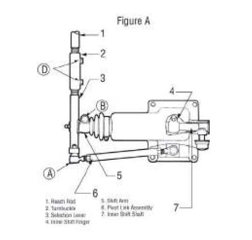
3.Remove the Cotter Pin, Castle Nut and Ball Joint A (see figure A) from the Selection Lever. Do not remove the Ball Joint from the Pivot Link.
4.Loosen the Cap Screw B (see figure A) and remove the Shift Arm from the inner Shift Shaft. Do not disconnect the Selection Lever from the Shift Arm.
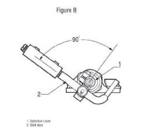
5.Turn the Shift Arm until it is at a right angle (90°) to the Selection Lever as viewed from the side (see figure B).
Note: Ideally, the Shift Arm should be adjusted 90° to the Selection Lever as described, but in some Chassis configurations it may be necessary to index the Shift Arm in the vertical position. Indexing the
Shift Lever is done to prevent Shift Lever jump out.
This type of adjustment will cause an unequal amount of Gear Shift Lever travel between Neutral and a forward lever position as compared to Neutral and a rearward lever position.
6.Install the Shift Arm on the Splines of the inner Shift Shaft.
You may have to move the Shift Arm 4° or 5° to align the Splines of the two parts. Disregard any movement of the Gear Shift Lever at this point. The Gear Shift Lever will be adjusted later.
7.Tighten the Cap Screw B (see figure A) on the Shift Arm.
8.Connect the Pivot Link assembly Ball Joint to the Selection Lever. Secure it with the Castle Nut and Cotter Pin.
9.Loosen the Jam Nuts C (see figure C) on the Pivot Link.
10.Check to be sure the inner Shift Finger is still in place.
11.Rotate the Pivot Link until the curved end of the Selection Lever is parallel with the Shift Arm as viewed from the rear (see figure C).
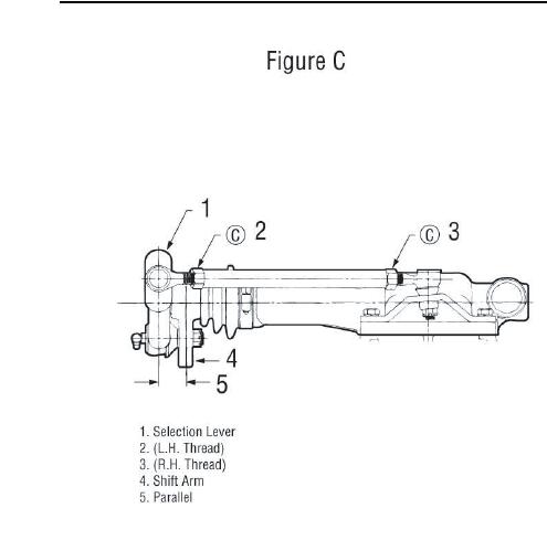
12.Tighten the Pivot Link Jam Nuts C (see figure C).
13.Loosen both Cap Screws on the Turnbuckle D (see figure A).
14.Check to be sure inner Shift Finger is still in place.
15.Rotate the Turnbuckle to obtain the proper forwarbackward Neutral position of the Gear Shift Lever in the cab.
16.Tighten one Turnbuckle D Cap Screw (see figure A).
17.Move the Gear Shift Lever to the desired position.
18.Turn the second Turnbuckle D Cap Screw.
19.Check for linkage obstructions in all gear positions.
EATON ServiceRanger 4.8 and 4.2 + Activator Free Download