It is essential that both Countershaft Assemblies of the Front and Auxiliary Sections are “timed.” This assures proper tooth contact is made between Mainshaft Gears seeking to center on the Mainshaft during torque transfer and mating Countershaft Gears that distribute the load evenly. If not properly timed, serious damage to the Transmission is likely to result from unequal tooth contact causing the Mainshaft Gears to climb out of equilibrium.
Eaton Service Ranger 4.8 2021 Diagnostic Software Installation Service
Timing is a simple procedure of marking the appropriate teeth of a gear set prior to installation and placing them in proper mesh while in the Transmission. In the Front Section, it is necessary to time only the Drive Gear set. And depending on the model,only the LO Range, Deep Reduction, or Splitter Gear Set is timed in the Auxiliary Section.
Procedure – Front Section
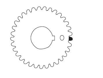
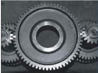
1.Marking Countershaft Drive Gear teeth: Prior to placing each Countershaft Assembly into the Case, clearly mark the tooth located directly over the Drive Gear Keyway as shown.
This tooth is stamped with an “O” to aid identification.
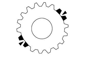
2.Marking Main Drive Gear teeth: Mark any two adjacent teeth on the Main Drive Gear.
Mark the two adjacent teeth located directly opposite the first set marked on the Main Drive Gear. As shown to the left, there should be an equal number of unmarked gear teeth on each side between the marked sets.
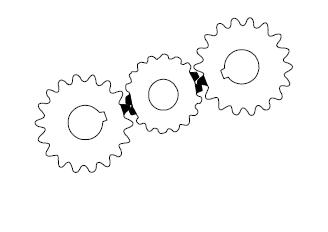
3.Meshing marked Countershaft Drive Gear teeth with marked Main Drive Gear teeth: After placing the Mainshaft Assembly into the Case, the Countershaft Bearings are installed to complete installation of the Countershaft Assemblies.
When installing the bearings on the left Countershaft, mesh the Countershaft Drive Gear marked tooth with either set of Main Drive Gear two marked teeth.Repeat the procedure when installing the Bearings on the Right Countershaft, make use of the remaining set of Main Drive Gear two marked teeth to time assembly.
Procedure – Time the RT Auxiliary Section
1.Mark a tooth on the Reduction Gear with a highly visible paint, preferably a yellow or white.
2.Mark a second tooth 180 degrees away from the first.(Ensure the marks are in the correct position by counting the teeth between them. You should have exactly the same number of teeth on the Reduction Gear between the marked teeth).
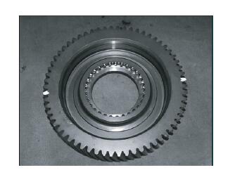
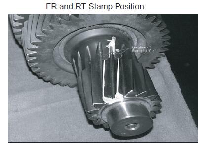
3.Locate the two stamped “O’s” on the Countershaft Reduction Gears and mark both teeth with a highly visible paint, preferably a yellow or white.
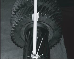
4.Use a Round File or Bar to properly align from the marked teeth on the Auxiliary Countershaft to the Auxiliary Splitter Gear. When the Bar is lined up with the root, between the correct teeth, you will notice it’s parallel with the Auxiliary Countershaft. Mark both the teeth with a highly visible paint.
Example of correct alignment Bar in correct position parallel with the Countershaft, and between the marked Splitter gear and Reduction Gear teeth.
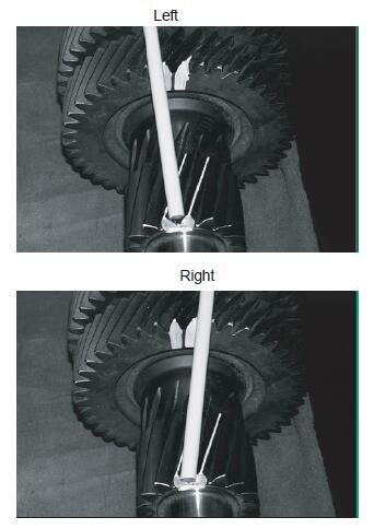
Examples of Left or Right Misalignment
5.Lay the Splitter Gear on a flat surface and mark it similar to steps 1 and 2 of this procedure. (Make sure the teeth are painted on both faces of the Splitter Gear front and rear).
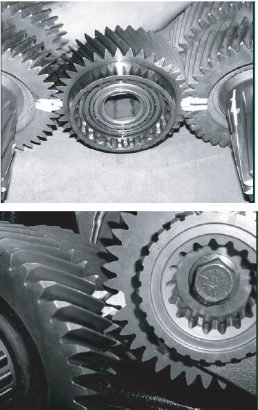
Example showing correct view of Reduction Gear timed to Countershaft Gears on the bench:
6.Install the Reduction Gear and Output Shaft Assembly into the Auxiliary Case. Then, install the Auxiliary Countershafts and Splitter Gear. (Countershaft Retaining Straps must be used to hold the Auxiliary Countershafts in place until the Auxiliary Section is fully installed. Failure to use the straps could result in the Auxiliary Section moving out of time).
Examples of Splitter Gear timed to the Auxiliary Countershafts:
7.To ensure the timing is correct, check that the marked tooth on the Splitter Gear is between the two marked teeth on the Auxiliary Countershaft Gears as shown in the illustrations:
EATON ServiceRanger 4.8 and 4.2 + Activator Free Download