This instruction show you guide on how to remove and install fuel injection pump for Bobcat Utility 3450 vehicle.
Related Contents:
2023 Bobcat Service Analyzer 91.15 91.05 Diagnostic Free Download
Procedures:
Fuel Injection Pump Removal:
Notice: Do not bend the high pressure fuel injection tubes when removing or installing them.
Do not attempt to maintain or adjust unless you are trained and have the correct equipment.
NOTE: When you remove any fuel system component to perform maintenance (such as changing the fuel filter), put an approved container under the opening to catch the fuel.
NOTE: NEVER use a shop rag to catch the fuel.
Vapors from the rag are flammable and explosive. Wipe up any spills immediately.
NOTE: NEVER use diesel fuel as a cleaning agent.
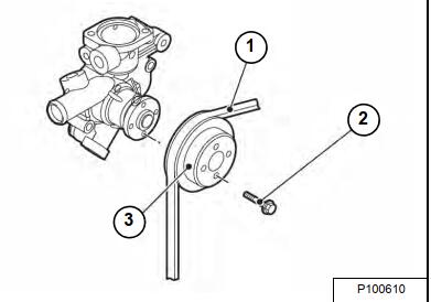
Loosen the cooling pump V-belt (Item 1) by loosening the alternator.
Remove the engine pulley guard (if equipped), engine cooling pulley bolts (Item 2), V-pulley (Item 3) and V-belt.
Close any fuel valves in the fuel supply line.
Place a drain pan under the fuel injection pump to catch any spillage.
Clean the area to keep contaminants from entering the fuel system.
Remove the high-pressure fuel injection lines as an assembly. (See High-Pressure Fuel Injection Lines
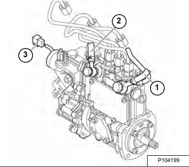
Disconnect the fuel return lines from the fitting on the fuel injection pump (Item 1).
Plug the open ends of the lines to minimize leakage and prevent contamination.
Remove the fuel supply line (Item 2) from the fitting on the fuel injection pump.
Plug or cap all openings to minimize leakage and prevent contamination.
Remove the throttle cable from the fuel injection pump.
Disconnect the stop solenoid wiring connector (Item 3)
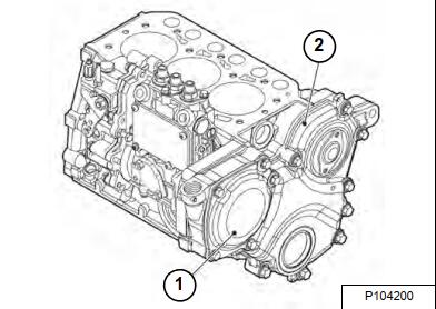
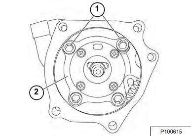
Remove the fuel injection pump drive gear access cover (Item 1) from the gear case cover (Item 2) NOTE: The cover is secured with an adhesive sealant. Use a gasket scraper to separate the cover from the gear case cover.
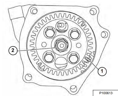
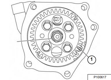
To aid in assembly, make alignment marks (Item 1) on the pump drive gear and idler gear.
NOTE: Mark the gears with something that will not rub off or be affected by oil and become illegible. If the gears are not marked or are illegible during installation, the gear case
cover must be removed to properly time the injection pump gear.
NOTE: After marking the position of the pump drive gear, do not rotate the engine crankshaft.
Rotating the crankshaft will cause the fuel injection pump to become misaligned.
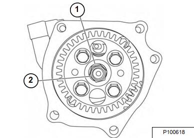
Hold the gear train stationary using a wrench on the crankshaft pulley bolt. Remove the fuel injection pump drive gear retaining nut and washer (Item 2)
NOTE: Do not loosen or remove the four bolts retaining the fuel injection pump drive gear to the fuel injection pump hub. Do not disassemble the fuel injection pump drive gear from the hub.
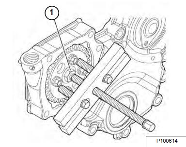
Thread the drive gear nut onto the injection pump shaft until it is even with the end of the shaft. This will prevent the gear from falling off of the shaft when using the puller.
Remove the injection pump drive gear and hub from the injection pump drive shaft as an assembly using an appropriate gear puller.
Once the fuel injection pump drive gear and hub assembly have “popped” loose from the tapered fuel injection pump drive shaft, carefully remove the drive gear nut (Item 1) and remove gear and
hub assembly.
Remove the four bolts (Item 1) and metal gasket (Item 2) fastening the fuel injection pump to the cylinder block. Remove the fuel injection pump.
NOTE: Do not rotate the crankshaft with the injection pump removed.
If the fuel injection pump requires servicing, it must be sent to an authorized Yanmar FIE repair facility for repair and calibration, or replaced with a new fuel injection pump.
NOTE: NEVER remove or attempt to remove the tamper-proof devices from the full-load fuel adjusting screw or the high-speed throttle limit screw on the fuel injection pump and governor assembly. These adjustments have been made at the factory to meet all applicable emissions regulations and then sealed.
NOTE: NEVER attempt to make any adjustments to these sealed adjustment screws. If adjustments are required, they can be made only by a qualified fuel injection shop that will ensure the injection pump continues to meet all applicable emissions regulations, and then replace the tamper-proof seals. Tampering with or removing these devices may void the “Limited Warranty.”
Fuel Injection Pump Installation
Install a new gasket to the mounting surface of the injection pump.
Install pump to the engine block using the four bolts (Item 1) and metal gasket (Item 2).
Tighten the bolts to 23 – 28 N•m (17 – 21 ft-lb) torque.
NOTE: Ensure the tapered surface of the fuel injection pump shaft is clean and dry.
Align the key on the fuel injection pump shaft with the keyway in the fuel injection pump drive gear hub. Ensure the fuel injection pump drive gear is aligned with the idler gear using the reference marks made earlier (Item 1)
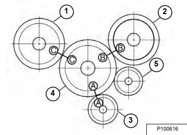
1 – Fuel Injection Pump Drive Gear
2 – Camshaft Drive Gear
3 – Crankshaft Drive Gear
4 – Idler Gear
5 – Oil Pump Gear
If installing the fuel injection pump on an engine with the front gear case cover removed, the fuel injection pump drive gear can be aligned with the idler gear by aligning the stamped marks (A, B, C) on the fuel injection pump drive gear, idler gear, camshaft gear and crankshaft drive gear. Ensure all three timing marks (A,B,C) are aligned [Figure 50-70-13].
Install the fuel injection pump drive gear lock washer (Item 1) and nut (Item 2) [Figure 50-70-14]. Do not lubricate threads of the nut or shaft. Hold the crankshaft pulley bolt with a wrench and tighten the pump drive gear nut to 59 – 69 N•m (44 – 51 ft-lb) torque.
Connect the fuel supply and return lines to the fuel injection pump.
More repair topic for Bobcat,please refer to:Bobcat Excavator Repair