Symptom: Transfer case oil temperature gauge inoperative. All other gauges are operational.
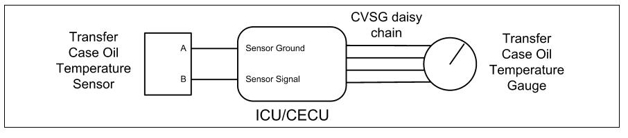
The Transfer Case Oil Temperature Gauge uses a thermistor sensor to measure the oil temperature.
The following procedures have been developed to assist the technician in diagnosing multiplexed instrumentation problems using the Electronic Service Analyst (ESA) hardware/software
diagnostic tool. It is assumed the service technician performing instrumentation repairs is knowledgeable about how to use ESA.
Related Content:
2021 Paccar ESA Electronic Service Analyst v5.4.3 v5.2.2 Free Download
Procedures:
Step 1:
Turn ignition key ON.
Start ESA, then select “Connect” to establish communication to the vehicle
Step 2:
Select “Monitor.” From
The “Components” window, select “Transfer Case Oil Temperature,” then select “Open.
Gauge graphic on screen displays reasonable reading go to Step 3
Gauge graphic on screen does not display reasonable reading go to Step 4
Step 3:
Select “Simulate”. Drag the “Value” bar until the pointer on the gauge image is approximately midscale. Observe vehicle gauge movement
Vehicle gauge does not move. Go to Step 3-1.
Vehicle gauge reading is in the same range as the ESA gauge image. Go to Step 3-7
Perform the following checks:
NOTE: For vehicles with a CECU, use the “Program” feature in ESA to make sure that the parameter for the inoperative gauge is enabled.
An inoperative gauge may simply have its CECU parameter set to disabled.
- Check CVSG data link wiring: Observe Gauge position in the wiring daisy chain.
- If gauge is mounted between two other functioning gauges CVSG data link wiring is OK. Go to Step 3-5.
- If gauge is last gauge in daisy chain or followed by other non-functional gauges, go to Step 3-2.
- Check continuity between Pin 1 on gauge harness connector and Pin 14 of the 52 Pin ICU/CECU connector C.
- Check continuity between Pin 3 on gauge harness connector and Pin 15 of the 52 Pin ICU/CECU connector C.
- Repair daisy chain jumper harness as necessary.
- Once continuity on both wires exists, perform “Simulate” test again.
- If gauge functions properly during “Simulate” test, repair is complete.
Return truck to service.
- If gauge does not function during “Simulate” test, install a known good gauge and perform “Simulate” test again.
- If gauge functions properly test is complete. Install new gauge permanently. Re-test and return truck to service.
- If gauge does not function during “Simulate” test, install Test ICU/CECU and perform “Simulate” test again.
(1) If gauge functions properly test is complete. Install new ICU/CECU permanently. Re-test and return truck to service.
(2) If gauge does not function properly during “Simulate” test, replace gauge.
- Once gauge is replaced.
- Verify gauge functionality.
- Return truck to service.
- Is this a recheck after Step 5, Step 6 or Step 7?
- Yes. Return truck to service.
- No, Gauge and CVSG data link wiring is not the problem. Go to Step 4
Step 4:
Select “Diagnose” to view transfer case oil temperature gauge diagnostic trouble code
DTC 138803 displayed – Open in transfer case oil temp circuit.
Indicates the problem could be an open in the wiring from the ICU/CECU to the sensor or a defective sensor. Go to Step 5, and if necessary, Step 6
DTC 138804 displayed – Short in transfer case oil temp circuit.
Indicates the problem could be a short to ground in the wiring from the ICU/CECU to the sensor or a defective sensor. Go to Step 5, and if necessary,Step 7.
Step5:
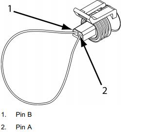
Unplug oil temperature harness connector at sensor.
Using a digital multimeter, check continuity on ground and signal wire at sensor connector.
Pin A – Ground Pin B – Signal
See Harness Interface
Diagrams for possible sensor locations.
See Connector
Identification for position and identification of the electrical connectors of
ICU/CECU.
See ICU/CECU Pinout for terminal details of the ICU/CECU electrical connections
(Sensor Ground) – There should be continuity between the sensor connector ground wire (Pin A) and a cab ground terminal.
(Signal) – There should be continuity between the sensor connector signal wire (Pin B) and
Pin 26 of the 52 Pin ICU/CECU connector C.
Check for continuity between sensor connector Pin A and firewall ground stud.
a. If there is continuity between Pin A and the ground terminal, test is complete. Go to Step 5-2.
b. If there is no continuity between Pin A and the ground terminal,repair wiring as necessary. Go to Step 5-1.
2. Check for continuity between sensor connector Pin B and Pin 26 of the 52 Pin ICU/CECU connector C.
a. If there is continuity between Pin B and Pin 26, test is complete . Go to Step 6.
b. If there is no continuity between Pin B and Pin 26 at ICU/CECU,repair wiring as necessary. Go to Step 5-2.
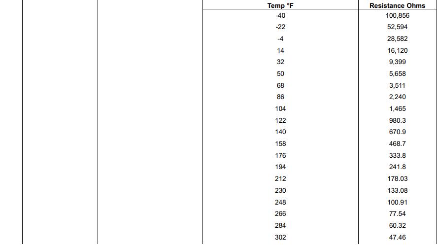
Alternate test method: Resistance in the oil temperature sensor (thermistor) signal wire changes as oil temperature increases/decreases.
1. By unplugging the oil temperature sensor harness connector and connecting a resistor decade box (i.e., Ametek PST2000 Tester), or an appropriate resistor to Pins A and B, you can simulate the sensor by dialing in a known resistance.
2. Observe vehicle gauge reading on dash.
3. If gauge needle moves to approximately the same temperature as in the table below, the problem is a defective oil temperature sensor. See table below.

Step 6:
Select “Diagnose” to view transfer case temperature gauge DTCs.
Unplug oil temperature harness connector at sensor.
See Harness Interface Diagrams for possible sensor locations.
See Connector
Identification for position and identification of the electrical connectors of ICU/CECU.
See ICU/CECU Pinout for terminal details of the ICU/CECU electrical connections
DTC 138803 – Open in transfer case oil temp circuit is displayed as “Active.
1Using a jumper wire, jump across sensor harness connector Pins A and B. If an “Active” DTC 138804 – Short in transfer case oil temp circuit is now displayed, you have confirmed there is not an open in the sensor signal wire to the ICU. The original fault (DTC 138803) was logged because there is an open in the oil temperature sensor itself, not the wiring. Go to Step 2.
bIf DTC 138804 is not displayed, there is an open circuit in the signal wire between sensor connector Pin B and Pin 26 of the 52 Pin ICU/CECU connector C. Repair wiring as necessary. Go to Step 2.
Alternate test method: Check for continuity between sensor connector Pin B (sensor signal) and Pin 26 of the 52 Pin ICU/CECU connector C.
1If there is no continuity, repair wiring as necessary. After repairs, DTC 138803 should now be displayed as “Inactive.”
2If there is continuity between sensor connector Pin B and Pin 26 of the 52 Pin ICU/CECU connector C, the open circuit is in the sensor itself,not in the wiring. Replace sensor
Step 7:
Select “Diagnose” to view transfer case oil temperature gauge DTCs.
Next, unplug the oil temperature harness connector at sensor.
See Harness Interface Diagrams for possible sensor locations.
See Connector Identification for position and identification of the lectrical connectors of
ICU/CECU.
See ICU/CECU Pinout for terminal details of the ICU/CECU electrical connections
DTC 138804 – Short in transfer
case oil temp circuit is displayed as “Active”
A If the fault is still “Active” after unplugging the sensor connector, you have confirmed there is a short to ground between Pin B (sensor signal) and Pin 26 of the 52 Pin ICU/CECU connector C.
1Check for a pinched or chaffed wire between Pin B (sensor signal) and Pin 26 of the 52 Pin ICU/CECU connector C. Repair wiring as necessary. Go to Step 2
DTC 138804 – Short in transfer case oil temp circuit is now displayed as “Inactive.
If DTC 138804 changes to “Inactive” after unplugging the sensor connector, you have confirmed the problem is a short in the sensor itself, not the wiring.
1 Replace sensor. Go to Step 2