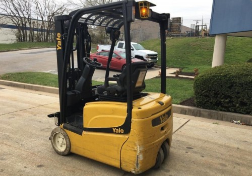
This instruction show you guide on how to remove and install parking brake and traction motor for YALE G807 ERP18VT lift truck.More repair case for Yale truck forklift,please refer to:YALE Forklift Trouble Repair.
Related Contents:
2023 Yale PC Service Tool 5.1 4.9 Free Download
Hyster PC Service Tool 2021 2018 v4.97 v4.93 Free Download
Procedures:
WARNING
Cleaning solvents can be flammable and toxic and can cause skin irritation.When using cleaning solvents, always follow the solvent manufacturer’s recommended safety procedures.
WARNING
The traction motor is heavy. Be sure that all lifting devices are suitable and of adequate capacity to lift the traction motor.
1.Position transaxle on blocks with studs down. Securely support in this position.
2.Remove parking brake assembly from traction motor:
Remove four capscrews, lockwashers, and washers holding brake assembly on traction motor.
Pry evenly on opposite sides to remove brake assembly from brake hub. Remove brake assembly by hand.
Remove snap ring holding brake hub on traction motor shaft. Slide hub from shaft. Remove snap ring and woodruff key from beneath hub.
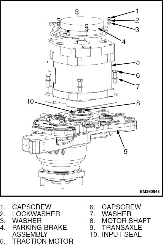
3.Remove traction motor from transaxle:
Install an eyebolt to traction motor shaft and attach an overhead lifting device of adequate
capacity to eyebolt.
Remove four capscrews and washersmounting traction motor to transaxle.
Lift traction motor from transaxle using overhead lifting device.
INSTALL PARKING BRAKE AND
TRACTION MOTOR
WARNING
Cleaning solvents can be flammable and toxic and can cause skin irritation. When using cleaning solvents, always follow the solvent manufacturer’s recommended safety procedures.
WARNING
The traction motor is heavy. Be sure that all lifting devices are suitable and of adequate capacity to lift the traction motor.
1.Position transaxle on blocks with studs down. Securely support in this position.
2.Install traction motor on transaxle:
Install an eyebolt to traction motor shaft and attach an overhead lifting device of adequate capacity to eyebolt.
Lightly lubricate inside lip of transaxle input shaft with multipurpose grease to ensure seal seats properly on traction motor shaft. It is not necessary to lubricate traction motor shaft as it is lubricated internally within the transaxle.
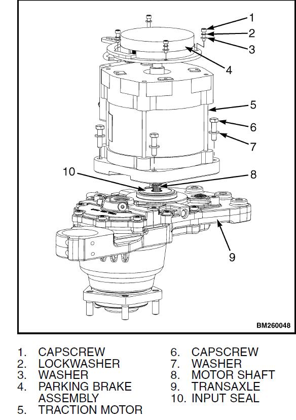
Lift traction motor and position it on transaxle using overhead lifting device. Guide traction motor shaft into transaxle through input seal.
Align motor with transaxle.
Install four capscrews and washers mounting traction motor on transaxle. Tighten capscrews to 48 N•m (35 lbf in).
Remove eyebolt from traction motor shaft.
3.Install parking brake assembly to traction motor:
Install lower snap ring and woodruff key on traction motor shaft. Align groove in hub with woodruff key and slide hub onto shaft. Install upper snap ring holding brake hub onto traction
motor shaft.
Position brake assembly onto brake hub. Align splines and seat brake on traction motor end head.
Install four capscrews, lockwashers, and washers to secure brake assembly. Tighten capscrews to 8 N•m (71 lbf in).
INSTALL TRANSAXLE TO FRAME
1.Check that dowels are installed in transaxle housing and are in good condition. Replace as necessary.
WARNING
The transaxle and traction motor assembly are heavy. Be sure that all lifting devices are suitable and of adequate capacity to lift the transaxle and traction motor.
2.Move transaxle assembly onto a floor jack using an appropriate sling and lifting device. Make sure assembly is balanced and properly supported so it will not fall during installation.
3.Carefully position transaxle on frame using floor jack. Align transaxle mounting dowels with their mounting holes in frame.
4.Apply Loctite® 271 to five socket head capscrews and washers. Install capscrews with washers through transaxle and into mounting holes in frame. Tighten capscrews to 220 N•m (162 lbf ft).
5.Remove cap and plug from service brake line and service brake port. Install service brake line to service brake port. Tighten to 12 to 16 N•m (108 to 192 lbf in).
6.Connect power cables to traction motor studs as tagged during removal. Tighten to 8 N•m (71 lbf in).
7.Connect traction motor temperature sensor connectors to main wiring harness.
8.Connect parking brake connector to main wiring harness.
9.Connect manual override cable to parking brakes.
10.Connect transaxle speed sensor connector to main wiring harness.
CAUTION
Make sure the lift truck is blocked at the same height as with the drive tire installed to ensure the proper fluid level reading.
11.Bleed the service brakes. Refer Brake System 1800 YRM 1332 for procedures.
12.Check fluid level in transaxle. Fill as necessary.
See Fluid Level Check.
13.Install drive tire and wheel assembly on wheel hub.
Install lug nuts and tighten to 170 N•m (125 lbf ft).
14.Connect battery connector, turn key switch to ON position, and test lift truck for proper operation.
15.Lower lift truck from the blocks.
ERP15-20VT (ERP030-040VT) (G807)
ERP16-20VF (ERP30-40VF) (A955)
16.Install mast on lift truck.
Masts 4000 YRM 1386 for European lift truck models
- ERP15-20VT (G807)
- ERP16-20VF (A955)
Masts 4000 YRM 1405 for European and American lift truck models
- ERP15-20VT (ERP030-040VT) (G807)
- ERP16-20VF (ERP30-40VF) (A955)