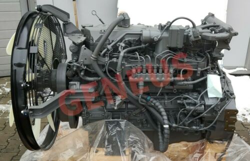
This instruction show you guide on how to diagnostic and diagnostics and solve JCB ISUZU 6HK1 engine U0073 (Flash Code 84) CAN-Bus malfunction J1939.

Preparations:
ISUZU E-IDSS 2024 2019 Engine Diagnostic Service System Free Download
Procedures:
U0073 Diagnostics
1.Turn OFF the ignition switch.
2.Measure the resistance between the terminals of the termination resistor harness connector.
Note: Make a measurement from the back with the harness connector connected.
Note: Confirm that the parallel resistance of the 120 Ω resistor in the termination resistor and that of the 120 Ω resistor in the ECM are both 60Ω.
Resistance:50.0 to 70.0 Ω
3.Disconnect the harness connector from termination resistor if the resistance value is outside the specified range.
4.Measure the resistance of the termination resistor.
Resistance:110.0 to 130.0 Ω
5.If the resistance value is outside the specified range, replace the termination resistor.
6.Connect the harness connector to the termination resistor .
7.Disconnect the harness connector from the control unit of the machine.
8.Measure the resistance between the terminals of the termination resistor harness connector.
Note: Make a measurement from the back with the harness connector connected.
Resistance:50.0 to 70.0 Ω
9.If the resistance value is within the specified range, replace the control unit of the machine.
10.Disconnect the harness connector from the ECM.
11.Measure the resistance between the terminals of the termination resistor harness connector.
Note: Make a measurement from the back with the harness connector connected.
Resistance:110.0 to 130.0 Ω
12.Replace the ECM if the resistance value is within the range of specified value.
13.Set the Injector ID Code and engine No. on the ECM.
14.Perform the unit difference learning of the fuel supply pump to the ECM.
15.Turn OFF the ignition switch.
16.Connect the harness connector to the ECM.
17.Turn ON the ignition switch.
18.Measure the voltage between the CAN-High terminal and GND of the termination resistor harness connector.
19.Measure the voltage between the CAN-Low terminal and GND of the termination resistor harness connector.
Voltage:1.5 to 3.5 V
20.If the voltage is outside the specified range, replace the ECM.
21.Set the Injector ID Code and engine No. on the ECM.
22.Perform the unit difference learning of the fuel supply pump to the ECM.
23.Turn OFF the ignition switch.
24.Connect the harness connector to the control unit of the machine.
25.Turn ON the ignition switch.
26.Measure the voltage between the CAN-High terminal and GND of the termination resistor harness connector.
27.Measure the voltage between the CAN-Low terminal and GND of the termination resistor harness connector.
Voltage:1.5 to 3.5 V
28.If the voltage is outside the specified range, replace the control unit of the machine.
29.If the voltage is within the specified range, replace the termination resistor.
2U0073 Confirm Resolution
1.Use the trouble diagnosis scan tool to clear the DTC.
2.Turn OFF the ignition switch for 30 seconds.
3.Start the engine.
4.Perform a test-run.
5.Use the trouble diagnosis scan tool to check if a DTC has been detected.
More repair cases for ISUZU engine,please refer to:ISUZU Engine Trouble Repair