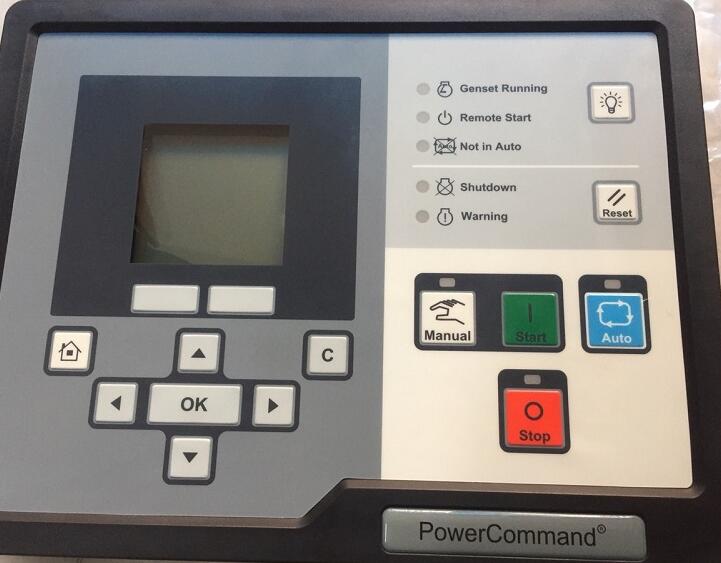
When PCC1302 Command engine speed too high,it comes trouble code 234 and shutdown.Here car-auto-repair.com show you guide on how to solve PCC1302 Command code 234 error.
Related Contents:
2023 InPower V14.5 Pro V12 Diagnostic Software Free Download
PowerCommand Diagnostic 9 Pin Adapter Cable for InPower
Logic:
Engine speed signals indicate an engine speed greater than shutdown threshold.
Possible Causes:
1 Fault simulation feature is enabled
2 Incorrect threshold setting
3 Incorrect fuel type setting
4 Faulty engine speed sensor connections
5 Faulty engine harness
6 Faulty extension harness
7 Faulty engine speed/position sensor
Diagnosis and Repair:
1 Fault simulation feature is enabled
a. Connect InPower
b. Verify that the fault simulation is not enabled for the engine speed sensor by connecting to the PCC via InPower. If the fault simulation is disabled, there is no problem.
2 Incorrect threshold setting
a. Connect InPower
b. Verify that fault threshold is within the normal operating range for the engine overspeed sensor. Refer to the engine manual for correct threshold values and make the appropriate changes using InPower.
3 Incorrect fuel type setting
a. Connect InPower
b. Verify the fuel source set with InPower is the same fuel used by the generator.
4 Faulty engine speed sensor connections
a. Inspect the engine speed sensor and the harness connector pins.
b. Disconnect the engine harness connector from the engine speed sensor.
c. Inspect for corroded pins, bent or broken pins, pushed back or expanded pins.
d. Inspect for evidence of moisture in or on the connector.
e. Inspect for missing or damaged connector seals.
f. Inspect for dirt or debris in or on the connector pins.
5 Faulty engine harness
a. Inspect the engine harness and the connector pins.
b. Disconnect the engine harness connector from the extension harness.
c. Inspect for corroded pins, bent or broken pins, pushed back or expanded pins.
d. Inspect for evidence of moisture in or on the connector.
e. Inspect for missing or damaged connector seals.
f. Inspect for dirt or debris in or on the connector pin.
g. Disconnect harness from ECM and sensor.
h. Measure the resistance in each pin from ECM to sensor. Resistance should be 5 ohms or less.
i. Repair or replace harness as necessary.
6 Faulty engine speed/position sensor
a. Inspect the engine speed sensor.
b. Disconnect the engine speed/position sensor from the engine and engine harness.
c. Inspect sensor for bent, corroded or loose pins.
d. Inspect the sensor for structural deficiencies.
e. Check the crankshaft speed sensor supply voltage.
f. Disconnect the engine harness connector from the crankshaft speed sensor.
g. Install the speed sensor breakout cable between the sensor and the sensor harness connector.
h.Measure the supply voltage by connecting the breakout cable’s supply and return connectors to the multimeter. If the reading is between 4.75 and 5.25 VDC, then the supply voltage is correct.
i. Check the crankshaft speed sensor signal (sense) voltage.
j. Disconnect the engine harness connector from the camshaft position sensor.
k. Install the speed/position sensor breakout cable between the sensor and the sensor harness connector.
l. Measure the signal voltage by connecting the breakout cable’s signal and return connectors to the multimeter. If the reading is between 0.46 and 4.56 VDC, then the signal voltage is correct. If not, sensor is faulty.