This instruction show you guide on how to repair Paccar Truck DTC257903 and DTC2577904 ammeter gauge inoperative.
Preparations:
Paccar ESA Electronic Service Analyst v5.4.3 v5.2.2 Free Download
Symptom:
Ammeter gauge inoperative. All other gauges are operational.
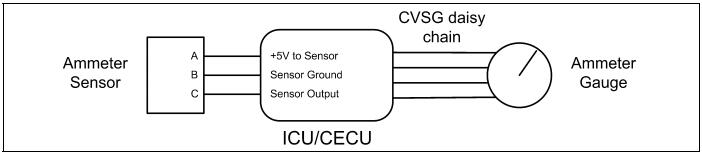
The Ammeter Gauge uses a contact less sensor using Hall Effect. The sensor is positioned on the cab feed wire inside the battery box, or for firewall mounted circuit breakers, near the firewall.
The following procedures have been developed to assist the technician in diagnosing multiplexed instrumentation problems using the Electronic Service Analyst (ESA) hardware/software diagnostic tool. It is assumed the service technician performing instrumentation repairs is knowledgeable about how to use ES
Procedures:
Step 1:
Turn ignition key ON.
Start ESA, then select “Connect” to establish communication to the vehicle
Step 2:
Select “Monitor.” From the “Components” window, select
“Ammeter,” then select “Open.”
Gauge graphic on screen display reasonable readings
Go to Step 3.
Gauge graphic on screen does not display reasonable reading
Go to Step 4.
Step 3:
Select “Simulate”. Drag the “Value” bar until the pointer on the gauge image is approximately mid-scale. Observe vehicle gauge movement.
Vehicle gauge does not move. Go to Step 3-1.
Vehicle gauge reading is in the same range as the ESA gauge image. Go to Step 3-7.
Perform the following checks:
NOTE:For vehicles with a CECU, use the “Program” feature in ESA to make sure that the parameter for the inoperative gauge is enabled.
An inoperative gauge may simply have its CECU parameter set to disabled.
1.Check CVSG data link wiring: Observe Gauge position in the wiring daisy chain.
a.If gauge is mounted between two other functioning gauges CVSG data link wiring is OK. Go to Step 3-5.
b.If gauge is last gauge in daisy chain or followed by other non-functional gauges, go to Step 3-2.
2.Check continuity between Pin 1 on gauge harness connector and Pin 14 of the 52 Pin ICU/CECU connector C.
3.Check continuity between Pin 3 on gauge harness connector and Pin 15 of the 52 Pin ICU/CECU connector C.
4.Repair daisy chain jumper harness as necessary.
5.Once continuity on both wires exists, perform “Simulate” test again.
a.If gauge functions properly during “Simulate” test, repair is complete.
Return truck to service.
b.If gauge does not function during “Simulate” test, install a known good gauge and perform “Simulate” test again.
i.If gauge functions properly test is complete. Install new gauge permanently. Re-test and return truck to service.
ii.If gauge does not function during “Simulate” test, install Test ICU/CECU and perform “Simulate” test again.
(1) If gauge functions properly test is complete. Install new ICU/CECU permanently. Re-test and return truck to service.
(2) If gauge does not function properly during “Simulate” test,replace gauge.
6.Once gauge is replaced
a.Verify gauge functionality.
b.Return truck to service.
7.Is this a recheck after Step 5, Step 6 or Step 7?
a.Yes. Return truck to service.
b.No, Gauge and CVSG data link wiring is not the problem. Go to Step 4
Step 4:
Select “Diagnose” to view “Active” ammeter diagnostic trouble codes
No “Active” DTCs displayed.
Indicates the problem could be a defective sensor, poor ground or no input or output voltage at sensor. Go to Step 5.
DTC 257903 displayed – Open in ammeter sensor circuit.
This DTC will be recorded when the control unit sees an open or short to ground at the secondary air pressure sensor input. The fault is recorded when
the voltage at the input is below .1 volts.
DTC 257904 displayed – Short in ammeter sensor circuit.
This DTC will be recorded when the control unit sees a short to +5V at the secondary air pressure sensor input. The fault is recorded when the voltage at
the input is above 4.9 volts
Step 5:
Using a digital multimeter, check the ground, input and output voltages at the sensor connector.
Pin A – Input Voltage
Pin B – Ground
Pin C – Output Voltage
See Harness Interface
Diagrams for possible sensor locations.
See Connector
Identification for position and identification of the electrical connectors of ICU/CECU.
See ICU/CECU Pinout for terminal details of the ICU/CECU electrical connections
Sensor Ground)-There should be continuity between the sensor connector ground (Pin B) and the firewall ground stud.
(Sensor Input Voltage) – Input voltage from ICU/CECU to sensor connector (Pin A) should be +5 volts.
(Sensor Output Voltage) – Signal output voltage at sensor connector
(Pin C) will vary depending on the amperage, but should be more than 0 volts and less than 5 volts.
See Table below.
NOTE:Do not unplug sensor connector to perform sensor output voltage check. Slide connector seal back to expose terminal ends.
Use test leads with needle point tips to probe connector terminals.
Average Range
120
60
0
-60
-120
Output Voltage
(VDC)
4.5
3.5
2.5
1.5
0.5
1.Check for continuity between sensor connector Pin B and ground terminal.
a.If there is continuity between Pin B and the ground terminal, test is complete. Go to Step 5-2.
b.If there is no continuity between Pin B and the ground terminal
i.Check for continuity between terminal B and Pin 9 of the 52
Pin ICU/CECU connector C.
ii.Check for continuity between Pin 5 of the 9 Pin ICU/CECU connector A and a cab ground terminal.
iii.Repair wiring as necessary. Go to Step 5-1.
2.Check input voltage at sensor connector Pin A.
a.If there is voltage at Pin A, Go to Step 5-3.
b.If there is no voltage at Pin A, check for voltage on Pin 1 of the 52
Pin ICU/CECU connector C.
i.If there is voltage on Pin 1, check continuity between Pin 1 at ICU/CECU and Pin A at sensor connector. Repair wiring as necessary. Go to Step 5-2.
ii.If there is no voltage on Pin 1 at ICU/CECU, replace ICU/CECU.
Go to Step 2.
3.Check signal output voltage at sensor connector Pin C.
a.If there is no voltage at Pin C, replace sensor. Go to Step 2.
b.If there is voltage at Pin C, check for voltage on Pin 9 of the 52 Pin ICU/CECU connector C.
i.If voltage is present on Pin 9 at ICU/CECU connector, replace ICU/CECU. Go to Step 2.
ii.If there is no voltage on Pin 9 at ICU/CECU connector, Go to Step 6.
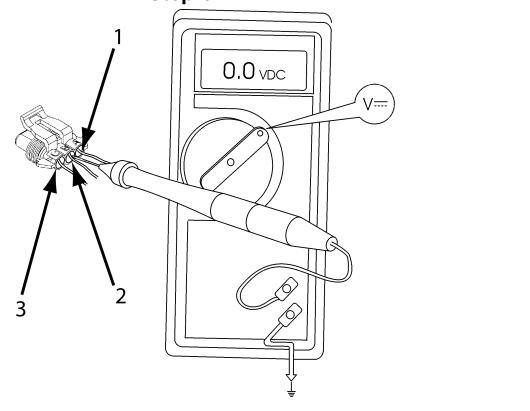
1Place MultiMeter Probe On Pin C
2Pin B
Step 6:
Select “Diagnose” to view ammeter gauge DTCs.
Next, unplug the ammeter connector at sensor.
See Harness Interface
Diagrams for possible sensor locations.
See Connector
Identification for position and identification of the electrical connectors of ICU/CECU.
See ICU/CECU Pinout for terminal details of the ICU/CECU electrical connections.
DTC 257903 – Open in ammeter sensor circuit is displayed as“Active.
1.Using a jumper wire, jump across sensor harness connector Pins B and C.
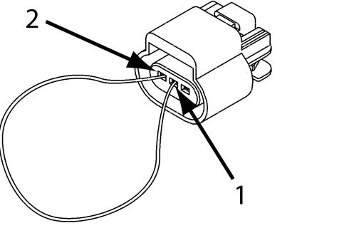
1Pin B
2Pin C
a.If an “Active” DTC 257904 – Short in ammeter sensor circuit is now displayed, you have confirmed there is not an open in the sensor output voltage wire to the ICU/CECU. The original fault (DTC 257903) was logged because there is an open in the ammeter sensor itself, not the wiring. Replace sensor. Go to Step 2.
b.If DTC 257904 is not displayed, there is an open circuit in the wire between sensor connector Pin C and Pin 9 of the 52 Pin ICU/CECU connector C. Repair wiring as necessary. Go to Step 2.
Alternate test method: Check for continuity between sensor connector Pin C (sensor output voltage) and Pin 9 of the 52 Pin ICU/CECU connector C.
1.If there is no continuity, repair wiring as necessary. After repairs, DTC257903 should now be displayed as “Inactive.”
2.If there is continuity between sensor connector Pin C and Pin 9 of the 52
Pin ICU/CECU connector C, the open circuit is in the sensor itself, not in the wiring. Replace sensor
Step 7:
Select “Diagnose” to view ammeter gauge DTCs.
Next, unplug the ammeter connector at sensor.
See Harness Interface
Diagrams for possible sensor locations.
See Connector
Identification for position and identification of the electrical connectors of ICU/CECU.
See ICU/CECU Pinout for terminal details of the ICU/CECU electrical connections.
DTC 257904 – Short in ammeter sensor circuit is displayed as “Active.
If the fault is still “Active” after unplugging the sensor connector, you have confirmed there is a short to ground between Pin C (sensor output voltage) and Pin 9 of the 52 Pin ICU/CECU connector C
Check for a pinched or chaffed wire between Pin C (sensor output voltage) and Pin 9 of the 52 Pin ICU/CECU connector C. Repair wiring as necessary. Go to Step 2
DTC 257904 – Short in ammeter sensor circuit is now displayed as Inactive.
If DTC 257904 changes to “Inactive” after unplugging the sensor connector, you have confirmed the problem is a short in the sensor itself, not the wiring.
Replace sensor. Go to Step 2