This instruction show you guide on how to remove and refit engine for IVECO Stralis Euro 3 truck.
If washing the engine bay, adequately protect the electric/electronic components and their connections.
Disconnect batteries by disconnecting the electric cables or by opening the current cut-out switch, lift the radiator cowling and overturn the cabin.
Related Contents:
Iveco EASY 13.1+KeyGen Software Free Download
2021 2019 IVECO Power EPC Spare Parts Catalogue Free Download
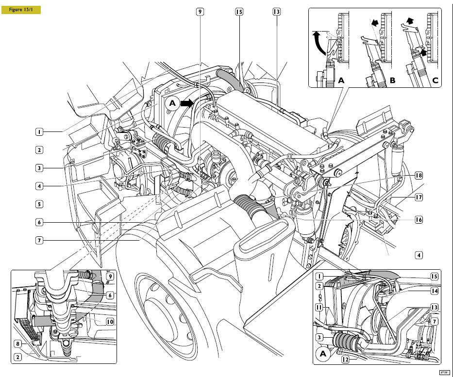
Operations to be carried out from the lower part:
– drain the cooling liquid in a fit container by removing the cap (8) from radiator (2);
– remove the line (10) between radiator and water pump union (9);
– disconnect line (5 and 6) from water pump union (9);
On the upper side:
– disconnect the air line (13) from the drier filter at union (7) after releasing it from the check clamp on the chassis;
– disconnect water lines (1 and 15) form the thermostat unit (14) (see detail A);
– disconnect the sleeve (3) connecting turbocharger to aftercooler radiator;
– if present, remove the climate control pipe (11) support bracket (12).
– disconnect the sleeve (18) connecting air filter line to turbocharger manifold;
– disconnect the exhaust line (16).
Unscrew the screws (17) fastening the engine supports to the flexible support (4) on the chassis.
– disconnect the connector from the electronic unit as follows:
- lift the safety lever;
- move the connector by disconnecting it from thecontrol unit;
- lift the connector by releasing the pawl.
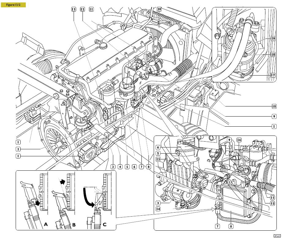
STRALIS
Carry out the following operations from the suction side:drain the power steering system oil in a fit container by disconnecting delivery and return lines (5 and 6). Disconnect electric connections (9 and 12) from the engine and release cable from the engine air suction manifold freeing it from check clamps. Disconnect the electric cables (14) and the ground cable (4) form the starter (3). Disconnect the electric cables (15) on the alternator (11). Disconnect pipe (13) on the compressor. Disconnect the sleeve (10) connecting aftercooler radiator – suction manifold. Disconnect fuel delivery and return lines (2 and 16). On vehicles fitted with climate control system, operate as follows: use the suitable wrench to operate the automatic backstand and remove the climate control system (19) compressor control belt (17).
Remove the screws (18) and the climate control system compressor. Without disconnecting the compressor pipes and to prevent draining the climate control system, fasten the compressor to the vehicle so that it does not interfere with the engine removal. Tighten the chains using a hoist and swing hoist 99360595 hooked to the engine brackets. Remove the engine fixing screws of the elastic engine (1) brackets from the chassis.
Slowly raise the engine from its compartment by taking it backwards so that the fan is released from the air conveyor compartment (20) on the radiator. Operate the screws to remove the fan from the hub. Remove the engine completely without interfering with the remaining fixed parts on the chassis, in particular the wiring interfering with the rear right engine support.
Refitting
In order to assemble the engine, carry out the operations described for disassembly in the reverse order, paying special attention to the operations required to install the assembly in the engine department and keeping to the following instructions:
check engine and gearbox group flexible supports and replace them if damaged. Check that exhaust line parts are not damaged or nearly damaged; if so, replace them. Tighten the screws and/or the nuts to the prescribed torque. Fill the cooling system with cooling liquid. Bleed the air supply system;
Tighten the nuts fastening the electric cables to the starting motor terminals, by applying the torque values below:
– nut M10 x 1.5 (terminal 30):
17.6 ÷ 24.5 Nm (1.8-2.5 Kgm);
– nut M5 x 0,8 (terminal 50):
2.6 ÷ 4.6 Nm (0.27-0.47 Kgm);
Fill the cooling system with coolant as described in the paragraph relevant. Blowair off the cooling systemas described in the paragraph relevant (operation 502011). Blow air off the fuel system as described in the relevant chapter (operation 542011). Fill the power steering circuit, then blow air off as described in the relevant chapter (operation 501030). Check the level of oil in the engine. Carry out the inspections and checks as described in the chapter relevant.
Connect connector (7) to control unit (8) as described below:
A, insert the pawl in its housing
B, connect the connector
C, push the safety lever until it stops.
Filling the cooling system
Preliminary operations
For vehicles equipped with just the standard cab heating system or manual air-conditioning:
– Fully open the coolant cock on the instrument panel.
For vehicles equipped with the automatic air-conditioning system:
– Set the temperature control in the cab on the HI position.
For vehicles equipped with an additional heater:
– The heater must not be turned on.
Operations
Place a sheet of cardboard between the coolant radiator and the intercooler radiator in order to shorten the time it takes to reach the engine’s working temperature (approx. 90°C).
Filling the system
GENERAL WARNINGS
Filling must be done with the engine cold.
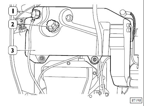
The cap (1) must not be removed for any reasons whatsoever.
To prevent pockets of air forming in the system, the fluid has to be transferred slowly (approximate flow rate 8 litres/min).
For vehicles equipped with an additional heater: the percentage of glycols in the coolant must be no greater than 50%.
After conscientiously following the above warnings,proceed as follows:
– Remove the cap (2) from the expansion tub (3).
– Pour the coolant into the expansion tub (3) till it is quite full.
Bleeding air from the system
For vehicles equipped with an additional heater:
– Turn on the heater.
Start the engine and keep the speed just above idling for 5 min.
If the tub empties completely during these first few minutes, stop and engine and top it up at a slower rate than before.
Restart the engine.
After 5 min. running, top up the level of fluid in the expansion tub, if necessary.
– Close the expansion tub filler with the cap (2).
Take the engine up to top speed so that the coolant quickly reaches the temperature of full thermostat opening (approx. 90°C) and keep it in this state until all the air is bled out of the system.
This is checked by seeing there is no foam or air bubbles in the tub.
The longest time it takes to bleed the air from the system completely is approximately 15 minutes from the moment when the thermostat opens (opening starts 85°±2° C).
Do not take the filler cap off the expansion tub until the fluid in the system has cooled completely.
Any topping up must only be done with the engine cold.
This is to avoid:
1 – Operator burns.
2 – Damage to the engine since cooling system pressurization is only created with the fluid heating from the condition of the engine cold.