Here is the step by step guide on how to remove and replace outlet check plugs for Perkins 1100 series engine model six and four cylinder engines, models PJ, PK, NH and NJ.
If the engine turns over but the engine does not start, refer to Operation and Maintenance Manual, ‘Fuel System – Prime’ and Troubleshooting, ‘Engine Cranks but Will Not Start’.
If the engine will not start, new service parts are available.
Related Contents:
Perkins EST 2024A & 2023A & 2019A Software Free Download
Perkins SPI2 2018A EPC+Service Manual Free Download
The new service parts are the following components:
Plug (Perkins part number 3346A013)
Pin (Perkins part number 2116A401)
Spring (Perkins part number 3174A032).
These parts are required for the installation procedure. If both check plugs require replacement, then a quantity of two of each component is required.
Removal Procedure
Warning! Contact with high pressure fuel may cause fluid penetration and burn hazards. High pressure fuel spray may cause a fire hazard. Failure to follow these inspection, maintenance and service instructions may cause personal injury or death.
Cautions:
Ensure that all adjustments and repairs that are carried out to the fuel system are performed by authorized personnel that have the correct training. Refer to Systems Operation, Testing and Adjusting, ‘Cleanliness of Fuel System Components’ for detailed information on the standards of cleanliness that must be observed during ALL work on the fuel system.
Care must be taken to ensure that fluids are contained during performance of inspection, maintenance,testing, adjusting and repair of the product. Be prepared to collect the fluid with suitable containers before opening any compartment or disassembling any component containing fluids. Dispose of all fluids according to local regulations and mandates.
Note: Put identification marks on all hoses and all plastic tube assemblies for installation purposes. Plug all plastic tube assemblies. This helps to prevent fluid loss and this helps to keep contaminants from entering the system. Ensure that cap kit (Perkins kit number U5MK1124) is used.
1 Turn the fuel supply to the off position.
2 Turn the battery disconnect switch to the off position.
Note: Perkins recommends the use of a clean sheet placed under the fuel injection pump. The clean sheet will assist in the prevention of the components falling onto the ground below the application.
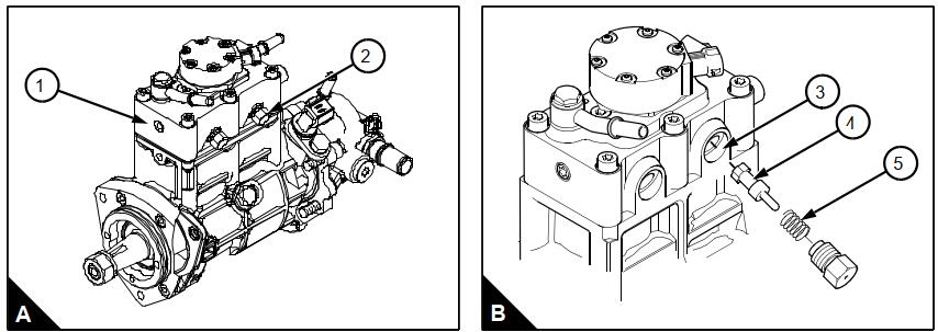
3 Remove one outlet check plug (A2) from fuel injection pump (A1). Remove the plug, the spring (B5) and the outlet check valve (B4).
4 Clean the components with alcohol or contact cleaner. Inspect the components for wear or damage. If there is damage to the radius surface of the outlet check valve, replace with a new outlet check valve.
5 Flush out the head of the fuel injection pump (A1) with clean alcohol or contact cleaner. Inspect the head of the fuel injection pump for damage or debris on the seat area (B3).
6 Use a cotton swab with alcohol or contact cleaner applied, swab threads in counterclockwise direction. This will remove debris from the threads.
Note: Caution is required to prevent pushing debris into the internal passages. Do not use a clockwise direction to clean debris from threads as debris could be pushed into the fuel injection pump.
Installation Procedure
Warning! Contact with high pressure fuel may cause fluid penetration and burn hazards. High pressure fuel spray may cause a fire hazard. Failure to follow these inspection, maintenance and service instructions may cause personal injury or death.
Cautions:
Ensure that all adjustments and repairs that are carried out to the fuel system are performed by authorized personnel that have the correct training. Refer to Systems Operation, Testing and Adjusting, ‘Cleanliness of Fuel System Components’ for detailed information on the standards of cleanliness that must be observed during ALL work on the fuel system.
Care must be taken to ensure that fluids are contained during performance of inspection, maintenance,testing, adjusting and repair of the product. Be prepared to collect the fluid with suitable containers before opening any compartment or disassembling any component containing fluids. Dispose of all fluids
according to local regulations and mandates.
Do not crank the engine continuously for more than 30 seconds. Allow the starting motor to cool for two minutes before cranking the engine again.
1 Crank the engine until fuel comes out of one of the plug orifices, free of air.
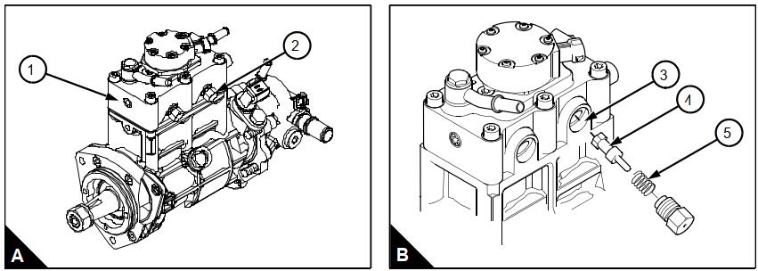
2 Replace the plug, spring (B5) and valve (B4). Tighten the plug finger tight.
3 Crank the engine again until the fuel comes out the outlet check plug orifice, free of air.
4 Tighten the outlet check plug (A2) finger tight. Tighten the outlet check plug (A2) to a torque of 40 Nm (30 lbf/ft) 4 kgf m.
5 Repeat steps 3 to 6 of the removal procedure for the other outlet check plug. Repeat steps 1 to 4 of the installation procedure for the other outlet check plug.
6 Turn the battery disconnect switch to the on position.
7 Turn the fuel supply to the on position.
8 Remove the air from the fuel system. Refer to Operation and Maintenance Manual, ‘Fuel System – Prime’ for the correct procedure.
9 Start the engine. Refer to Operation and Maintenance Manual, ‘Starting the Engine’ for the correct procedure. Check for fuel leaks.
Note: The threads can retain a small amount of fluid that will seep out during the early hours of operation and could be confused with a leak
More trouble repair case for Perkins,pls refer to:Perkins Trouble Repair