This illustration show you guide on how to use Volvo Techtool and oscilloscope to check Camshaft and flywheel signals for Volvo EC500F L5 excavator.
Related Contents:
2024 Volvo TechTool PTT 2.8.241 APCI 0.7.1.0/2.7.116 All Version Free Download
Volvo PROSIS 2023 2019 2018 Parts Catalog & Repair Manuals Free Download
Volvo Diagnostic Kit (88890300)
Volvo VOCOM 88890300 Diagnostic Kit
Procedures:
1.Place the machine in service position 1, refer to Service position.
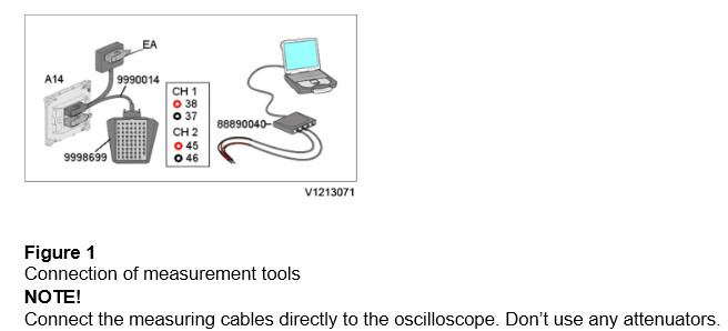
2.Connect Tech Tool Service Tool to the machine. Connect the tools according to the figure below.
3.Turn on the battery disconnector and start the engine.
4.Run operation 28420-3 Flywheel and camshaft signal, test. Select engine speed option and open the oscilloscope viewer.
NOTE!
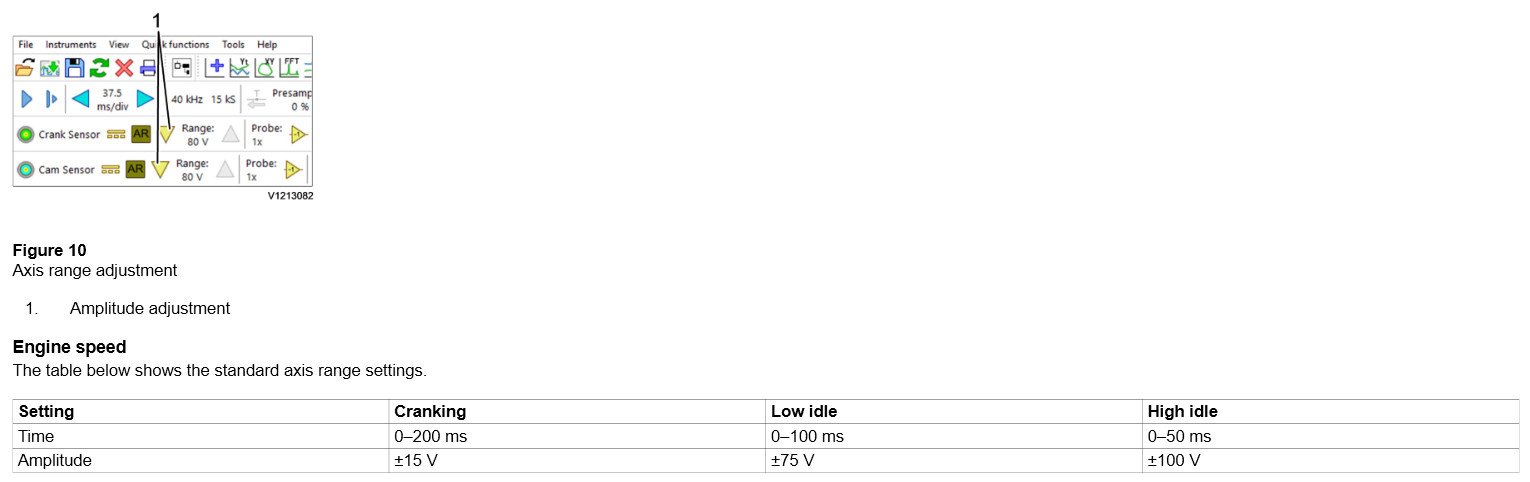
The different engine speed ranges will result in different oscilloscope settings.
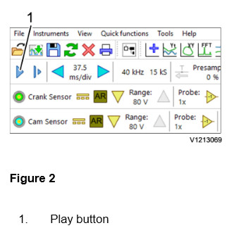
5.Use the play button to start or stop the oscilloscope readings.
NOTE!
The function “Save” overwrites the axis settings of the template file in Tech Tool. Therefore, use “Save as” to save readouts with changed settings.
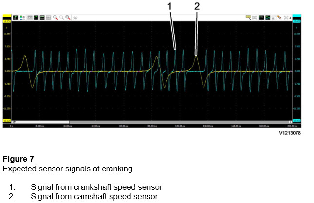
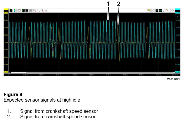
6.The camshaft has a tooth wheel with seven teeth. The seventh tooth is used to indicate that TDC (top dead centre) of cylinder one is close and is located just before the tooth of cylinder one (sometime referred to as double tooth).
The tooth wheel for the crankshaft is realized by cavities in the flywheel. At three locations on the flywheel there are no cavities with the purpose to create a visual gap in the signal. These gaps in the crankshaft sensor signal shall coincide with the peaks of the camshaft sensor signal.
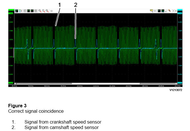
Check that the peaks of the camshaft speed sensor signal, except one, coincides with the gap of the signal from the crankshaft speed sensor.
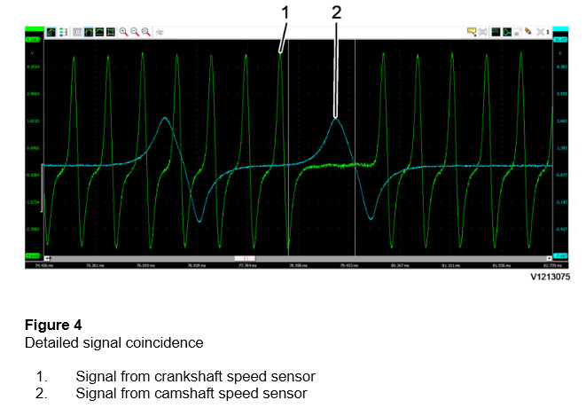
NOTE!
If the signals don’t coincide as shown in the figure, adjustment of the camshaft position is needed according to information in Camshaft setting, checking. The direction of adjustment is explained below.
NOTE!
In case of any issues with the sensors or the sensor installation, the signals shapes may not correspond to the figures. If there are any such problems, check the oscilloscope connections and also check the signals with different channels in the oscilloscope. It is also recommended to continue with the fault tracing according to the diagnostics.
7.Restore the machine.
Incorrect camshaft position examples
The figures below show how the signals coincide when the camshaft is incorrectly installed.
Each gear tooth of camshaft displacement corresponds to approx. 1.5 peaks in crankshaft speed sensor signal.
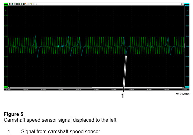
If the signal for the camshaft speed sensor is displaced to the left the camshaft is displaced at least one gear tooth in the camshaft’s rotational direction.
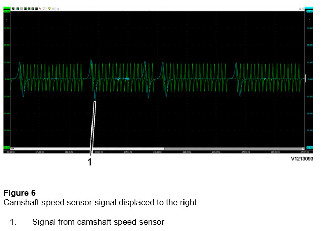
If the signal for the camshaft speed sensor is displaced to the right the camshaft is displaced at least one gear tooth opposite to the camshaft’s rotational direction.
Example of sensor signals at different engine speeds
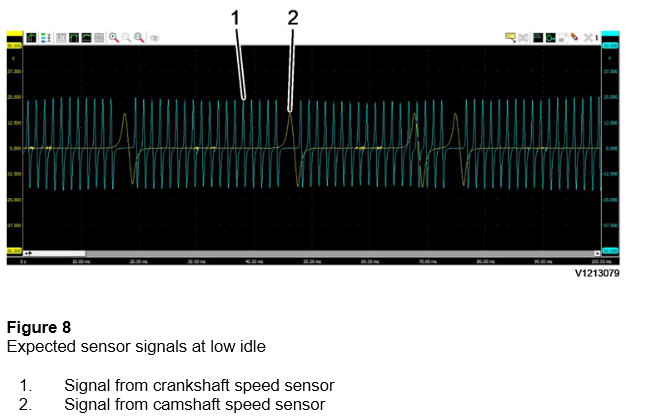
Signal amplitude
The amplitude (peak to peak voltage level) of the sensor signals varies with the engine speed and the distance between the sensor and the tooth wheel, hence the amplitude will differ from machine to machine. Adjusting the axis range will help in viewing in cases where the signal doesn’t fit the viewing window.
More repair case for Volvo machine,please refer to Volvo excavator trouble repair