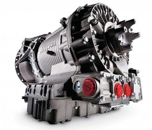
Here is the instruction show you guide on how to solve Allison 3000 & 4000 Gen5 transmission P0562 trouble codes system voltage low error.

DIAGNOSTIC RESPONSE:
Inhibit TCC Operation, DNA
For more Diesel machine repair,please refer to:
2023 Diesel DTC Solutions V2.9.98+ Diesel Explorer 2.0+Instruction
CIRCUIT DESCRIPTION:
The TCM requires a switched ignition voltage input to operate. The switched ignition voltage signal originates from the ignition switch or an ignition relay to supply voltage to wire 163 in the 80-way connector at the TCM.
The ignition sense power signal to terminal 63 turns the TCM ON from its power-down state. The TCM reads the calibration data, then commands the transmission and shift selector to N (Neutral).
After the ignition switch is turned OFF, the TCM powers-down when both input and output speeds are zero, and the appropriate data has been stored in memory. If the system has a display, the display goes blank after the process is completed. Unswitched battery power must be maintained during the power-down period.
NOTE: The TCM ignition power signal must be provided through a 5A, 10A, or 15A fuse, or a manually-reset circuit breaker.
ACTION TAKEN WHEN THE DTC SETS:
1 The TCM iluminates the CHECK TRANS light.
2 TCM may not re-initialize if ignition is turned OFF.
CONDITIONS FOR CLEARING THE DTC:
Use the diagnostic tool to clear the DTC from the TCM history. The TCM automatically clears the DTC from the TCM history if the vehicle completes 40 warm-up cycles without the DTC recurring.
DIAGNOSTIC AIDS:
1 DTC sets when ignition voltage is detected to be below 5V for a calibrated period of time with engine running.
2 A defective vehicle battery may allow this DTC to set. Test all vehicle batteries to OEM specifications for proper voltage and load capacity.
3 A defective vehicle charging system may cause this DTC. Test the charging system to all OEM specifications. Low voltage or electrically noisy alternators may prevent clean or ample ignition voltage from reaching TCM pin 63. If alternator performance is preventing clean ignition power on the vehicle, consider implementing the alternate ignition power diagram shown in OEM Tech Data.
4 Defective or unsuppressed components in the vehicle ignition system, such as the ignition switch, TCM ignition relay, ignition circuit connector problems, fuse holders, or noisy ignition signals may cause this DTC.
5 Ignition input to the TCM must be free of unsuppressed inductive loads, such as solenoids, relays and motors. If the source for ignition power is suspected to have unsuppressed load(s) attached, consider implementing the alternate method for providing ignition voltage to the TCM. Inductive noise or ignition or relay switch bounce can create noise on ignition W163 and may cause this code. Consider diode suppressing any component such as relays that are causing inductive load noise.
6 Ignition voltage is available on the diagnostic tool Data Monitor grid. Prior to ‘Connect’ for the diagnostic tool, check the Troubleshoot Specific Problem’ box under the “Connection Options” and then check the ‘Sensor, Voltage, Ohms, and Counts Data’ box.
7 The ignition power (W163) must stay powered continually during engine cranking, and during transition from the “crank” position of the start switch to the “ON” or “RUN” position. Once the engine is running, this wire must remain powered at all times in order to achieve proper operation of the relays which control the Neutral Start, Reverse Warning, and other transmission-related vehicle functions. This wire must not be powered in the accessory” position, as it may cause significant and unnecessary drain on the battery. Ignition power on W163 while in the accessory position may run the batteries down and cause this DTC.
8 Broken or defective connector assemblies allowing pushed back pins to short together.
9 Unlocked connectors, missing seal plugs allowing moisture in connectors.
Review applicable information in CONTROL SYSTEM AND TRANSMISSION SPECIFICATIONS to find additional circuit specifications, system and connector diagrams, and troubleshooting tips.
More Allison repair case,please refer to Allison Trouble Repair