The information in this Service Bulletin provides the troubleshooting procedure to follow when the alarm code A0052 is visible on the display screen.
When the alarm code A0052 occurs, it is no longer possible for the customer to log the yield data of the combine.
The alarms A0052 occurs if the output voltage of the yield sensor is outside the allowable voltage range.
This allowable voltage range depends on whether the unit has a:
Universal Control Module (UCM):
All CR from MY15 onwards with the harvest suite ultra cab.
All CX from MY16 onwards with the harvest suite ultra cab.
Combine Control Module (CCM):
All other combines without the harvest suite ultra cab.
Related Contents:
2024 CNH EST 9.10 9.2New Holland Diagnostic Software Free Download
ACTION
PRODUCTION
Not applicable.
SERVICE
Unit preparation
NOTE: The four reference points to the unit are the left-hand side, the right-hand side, the front of the unit, and the back of the unit. These reference points apply to someone that faces the direction of travel from a standing position that is behind the unit.
WARNING
Avoid injury!
Before you start any work on the unit, prepare the unit according to the following instructions.
Failure to comply could result in death or serious injury.
1 Thoroughly clean the area on the unit that pertains to the service instructions for this Service
Bulletin.
2 Park the unit on a hard, level surface.
3 Apply the parking brake.
4 Completely lower any attachments to the ground.
5 Relieve all of the hydraulic system pressure.
6 Shut down the engine.
7 Follow any specific instructions that pertain to the unit within the service instructions as necessary.
Service instruction CX and CR combines with the UCM controller:
NOTE: When troubleshooting an A-0052 alarm code on a combine with a UCM, it is important to first verify the part number of the yield sensor. The part number of the yield sensor will determine the specific troubleshooting steps to follow.
The part number of the yield sensor is on a white sticker on the top of each yield sensor.
Specific information for the yield sensor: – 47696978 sensors – 84185506 and/or 47613138:
The A-0052 alarm code occurs when the yield sensor output voltage is less than 0.2 V or greater than 6.2 V for more than 1 second.
NOTE: The below error codes can also display with the A-0052 alarm code:
– E0343-05: voltage less than 0.1 V
– E0343-03: voltage greater than 11.5 V
Specific information for yield sensor: – 47696978
The A-0052 alarm code will only occur when the yield sensor output voltage is less than 0.2 V.
NOTE: The yield sensor 47696978 has a maximum voltage limit of 5.5 V, so the sensor should not be able to reach the 6.2 V which is the high-side trigger point for the A-0052 alarm code.
Troubleshooting for all yield sensors:
Use the diagnostics screen on the combine display to monitor the voltage of the yield sensor with no crop passing through the machine. This voltage is known as the no-load voltage.
This can be selected under the “Settings” tab. The yield sensor is in Precision Farming System (PFS).group.
Applicable to yield sensors: 84185506, 47613138 and 47696978.
1 If the no-load voltage is low – greater than 0.1 V but less than 0.7 V:
A Check the position of the impact plate of the grain sensor. When harvesting large seed crops, for example, soybeans and corn, it is possible for grain to trap between the impact plate and the side of the elevator. If you confirm that there is trapped grain between the impact plate and the side of the elevator refer to:
ASiST knowledge item ID: 1024951 – ‘Inaccurate yield readings due to crop pinched near the elevator yield sensor’.
NOTE: This concern can be erratic and inconsistent because the amount of inaccuracy depends on how much grain traps between the impact plate and the side of the elevator.
This concern is also difficult to confirm because the trapped crop falls out when you fold out the yield sensor for inspection.
The best way to confirm this concern is to remove the clean-out door on the bubble-up auger housing, and use a light and inspection mirror to look up toward the impact plate of the grain sensor. This will enable you to see if there is any trapped crop around the impact plate.
B Check the area around the yield sensor for any signs of crop build up or debris that could affect the yield sensor voltage.
C Make sure that all yield sensor mounting hardware is installed correctly.
D Make sure that the front counterweight bolt does not contact the load-cell rod.
Change the M8 x 45 mm bolt to an M8 x 40 mm bolt if necessary. For additional information on this concern, refer to:
ASIST knowledge ID number 1020371 – ‘Yield sensor no-load voltage will not adjust due to contact at the counterweight bolt’.
E If the voltage is still low, use special tool 84446103 to adjust the yield sensor no-load voltage between 0.7 V and 0.9 V.
NOTE: If the no-load voltage is less than 0.1 volts (no voltage), it is possible that the yield sensor voltage becomes stuck below zero.
Once the no load voltage is below 0.01V, the displayed value of the yield sensor sticks until the voltage rises above 0.01V.
If you suspect that the yield sensor is stuck, attach special tool 84446103 to the yield sensor.
Refer to the service manual section 55 – “Harvest material flow control system – Adjust”
eTIM link: Grain flow sensor – Adjust (55.426.AA-F.45.A.01)
Press and hold the adjustment button for up to two minutes while you monitor the yield sensor voltage on the display diagnostics screen.
Once the voltage on the display begins to increase, try to release the switch when the voltage is between 0.7 V and 0.9 V. If the voltage over shoots this target, you can readjust it by pulsing the adjustment button.
F When the no load voltage value is set, you must check to see that the no load voltage value is saved. To carry out this check:
Turn the ignition key OFF
Wait until the monitor has completely shut down
Switch the ignition key ON
NOTE: If the voltage value is not yet in the correct range between 0.7 V and 0.9 V, the adjustment needs to be redone.
To memorize the no load voltage you must adjust the no load voltage in one direction by 0.5 V or more. Then wait 2 seconds and adjust the voltage back to between 0.7 V and 0.9 V. NEW HOLLAND recommends to do this by pulsing the adjustment button on tool 84446103 consecutively, as this action provides a more accurate control.
Example how to memorize the no load voltage:
No load voltage has been adjusted to 0.8 V, but is currently not memorized.
Apply nine pulses to the adjustment button on tool 84446103. The voltage will change in one direction by approximately 2.2 V.
Wait two seconds.
Apply nine pulses to the adjustment button on tool 84446103. The voltage will change in the opposite direction.
The no load voltage should have returned to 0.8 V.
The system will memorize this voltage.
Use the above key cycle to verify that the voltage is memorized.
NOTE: If for any reason the system has not memorized the voltage, repeat Step F.
Explanation of adjustment:
Figure 1 depicts a graph from a yield sensor with a no-load voltage below 0.01 V.
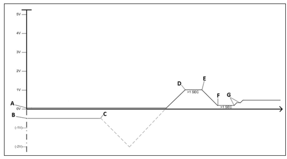
Line A is the minimum voltage from the display ( 0.01 V).
Line B is the actual no-load voltage of the yield sensor.
Point C depicts the press and hold function of the button on special tool 84446103.
NOTE: The voltage first drops to the minimum of the range and then starts to increase again.
Point D depicts the release of the button on special tool 84446103 when the voltage has started to change on the display.
NOTE: Point D – The no load voltage is now too high.
To reduce the no-load voltage:
Release the button on the special tool 84446103 for more than 1 second
Press and hold the button. Point E depicts the start of the voltage reduction
NOTE: Point E – The no load voltage is now too low. You now need to make small adjustments to raise the voltage slightly.
To make small adjustments to the yield sensor, you can pulse the button on the special tool 84446103.
Point G depict where there were two consecutive pulses of the button on the special tool 84446103, to achieve a voltage between 0.7 V and 0.9 V
NOTE: One single pulse changes the voltage by approximately. 20 mV.
NOTE: If the pause between the pulses on the button of the special tool 84446103 is more than 1 second, the direction of the voltage adjustment will change.
If the above procedure does not work, follow the troubleshooting for the
E0343-05 error code.
Troubleshooting for this error code will verify the yield sensor power circuits and ground circuits, as well as the signal circuit between the yield sensor and UCM2.
Applicable to yield sensors 84185506 and 47613138 only.
If the no-load voltage is high – greater than 6.2 V:
Use the special tool 84446103 to adjust the yield sensor no-load voltage to between 0.7 V and 0.9 V. The procedure to adjust the voltage is the same as above.
If you are unable to adjust the no-load voltage to the correct range, follow the troubleshooting for error code E0343-03. Troubleshooting for this error code will verify the yield sensor power circuits and ground circuits, as well as the signal circuit between the yield sensor and UCM2.
If the no-load voltage is correct (Step 1 above), but the display voltage is exceeds 6.2 V in high grain flow conditions:
Monitor the ‘Dry-Flow’ average parameter on the run screens.
NOTE: If the ‘Dry-Flow’ average value exceeds 125 – 135 tonnes/hr (4920-5315 bu/hr in corn), it indicates that the sensor is at the maximum operating capacity. In this case the A-0052 alarm code would be normal, and there would not be any fault in the yield sensor
However, to gain some additional sensor capacity (approximately 10% improvement), use the special tool 84446103 to adjust the yield sensor No-load voltage to 0.3 V.
CX and CR combines with CCM controllers
The A-0052 alarm code occurs when the yield sensor output voltage is less than 0.2 V or greater than 5.2 V for more than 1 second. The error codes E0288-05 (voltage less and 0.1 volts) or E0288-03 (voltage greater than 5.5 volts) may also display with the A-0052 alarm code.
Specific information for the yield sensors: – 84185506 and 47613138:
The A-0052 alarm code occurs when the yield sensor output voltage is less than 0.2 V or greater than 5.2 V for more than 1 second.
NOTE: The below error codes can also display with the A-0052 alarm code:
– E0288-05: voltage less and 0.1 V
– E0288-03: voltage greater than 5.5 V
Use the diagnostics screen on the combine display to monitor the voltage of the yield sensor with no crop passing through the machine. This voltage is known as the no-load voltage.
This can be selected under the “Settings” tab. The yield sensor is in Precision Farming System (PFS).group.
If the no-load voltage is low – greater than 0.1 V but less than 0.7 V:
Follow Steps 1A to 1E from the above instruction for combines with UCM controllers. If the issue persists proceed to the next step.
Follow the troubleshooting for the E0288-05 error code. Troubleshooting for this error code will verify the yield sensor power circuits and ground circuits, as well as the signal circuit between the yield sensor and the CCM3.
If the no-load voltage is high – greater than 5.2 V:
Use special tool 84446103 and follow the above procedure to adjust the yield sensor no-load voltage between 0.7 V and 0.9 V.
If you are unable to adjust the no-load voltage to the correct range, follow the troubleshooting for error code E0288-03. Troubleshooting for this error code will verify the yield sensor power circuits and ground circuits, as well as the signal circuit between the yield sensor and CCM3.
If the no-load voltage is correct, but the display voltage is exceeds 5.2 V in high grain flow conditions:
Monitor the ‘Dry-Flow’ average parameter on the run screens.
NOTE: If the the ‘Dry-flow average value exceeds 100 – 110 tonnes/hr (3935-4330 bu/hr in corn), it indicates that the sensor is at the maximum operating capacity. In this case the A-0052 alarm code would be normal, and there would not be any fault in the yield sensor
However, to gain some additional sensor capacity (approximately 10% improvement), use the special tool 84446103 to adjust the yield sensor No-load voltage to 0.3 V.
All combines
If the problem still exists after you perform the above checks, enter an ASiST Technical Help Desk (THD) report with the below information.
A copy of the Electronic Service Tool (EST) error code history for the combine. To do this:
Connect the EST to the combine
Navigate to the ‘Retrieve Controller Faults’ screen
Select the ‘Retrieve Faults From All Controllers’ button at the bottom of the screen
In the pop-up window select the ‘Save Information To Disk’ button
Save this file with the fault code information and attach it to your ASiST THD report
A copy of the EST software versions file for the combine. To do this:
Connect the EST tool to the combine
Navigate to the ‘Controller Status’ Screen
Select the ‘Retrieve Version Information From All Controllers’ button at the bottom of the screen
In the pop-up window select the ‘Save Information To Disk’ button
Save this file with the version information and attach it to your ASiST THD report
Provide the CN1 file from the USB key of the display, and identify below details for:
The grower
The farm
The field
The task
Confirm the crop and an estimate of the approximate crop yield, to compare what is on the CN1 file
Identify the specific header model and header size
More repair cases for New Holland machine,please refer to:New Holland Trouble Repair