This is a instruction show you on how to install HINO PTO interface for HINO model year 2015 & later with Allison 2500 with CS6B-A67**-S3*H PTO.Try this guide at your own risk!
Always read and understand the entire manual completely before installation or operation of pto and driven equipment including these warnings and operator’s instructions in section 3!
Related Contents:
2024.03 HINO Diagnostic Explorer DX3/DX2 Diagnostic Software Free Download
HINO Trucks EPC Electronic Parts Catalog 2018 2016 Free Download
Warnning:
Always disengage the pto when the driven equipment is not in operation
Do not attempt to install or service any power take–off with the truck engine running. put ignition keys in your pocket before getting under truck.
Do not allow truck engine to be started while workers are under truck.
Before working on a vehicle place transmission in neutral or park, set brakes, and immobilize truck wheels with suitable chocks.
Be sure to block any raised body or mechanism before working on or under equipment.
Iinstalled power take-offs must never be shifted in or out of gear by any means except by the controls in the cab of the truck.
Stay clear of spinning driveshafts to avoid becoming entangled and injured.
It shall be the responsibility of the installer of a muncie power take-off to decide whether to Install guards in the pto and/or driveline area because of potential exposure to danger. this is because most muncie ptos are installed by equipment distributors or manufacturers and therefore, the responsibility of the installation is beyond the control of muncie power products.
obtain proper training before operating this machinery.
Do not install or operate equipment which has not been properly specified for your vehicle.
Installers are to insure that pto components do not interfere with any chassis components, including but not limited to vehicle crossmembers, frame rails, driveshafts, exhausts, converters, fuel lines, etc. while vehicle is stationary or mobile.
Allow the vehicle, pto and driven equipment to warm up when operating in weather where temperatures are near or below freezing 32° f (0° c).
Install separate controls for pto and driven equipment.
Always install the safety labels provided and place the operator’s manual in the vehicle glove compartment
IMPORTANT:
Disconnect vehicle battery prior to installing electrical and electric/hydraulic activation kits.
Procedures:
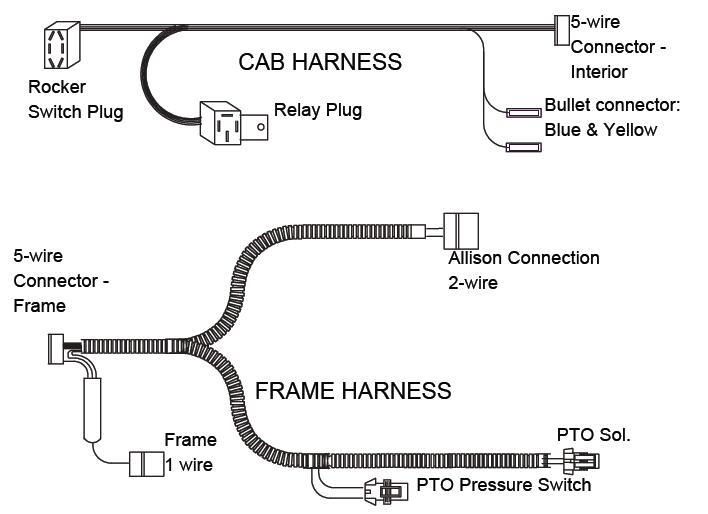
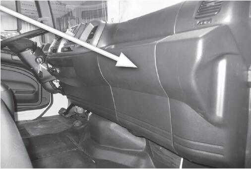
1.Locate the wiring harnesses provided in this kit. The harness can be separated into two sections. The section without the loom is for inside the cab. Pull the fuse access panel from the dash board.
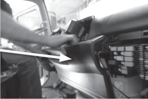
2.Remove the capscrews holding the dash board panel show. Then remove this panel.
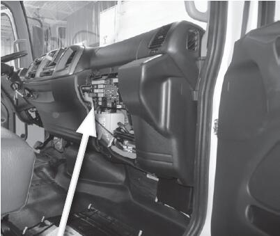
3.Using the Interior Cab wiring harness without the loom, make the connections to the vehicle connectors shown here.
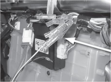
Locate the 5-WIRE connector
Locate the Bullet connectors
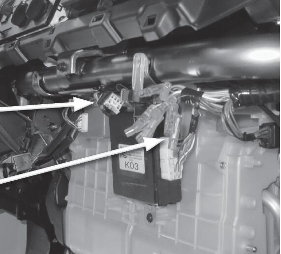
The 5-WIRE Connector from Muncie Harness – Interior.
This connection is the pass-through from the frame rail connection.
BLUE (large gauge) and YELLOW Bullet connection here
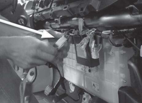
Route the Muncie Harness along the dash attaching it to the other harnesses along the front of the cab. Do not attach to structural members of the cab.
PTO Switch
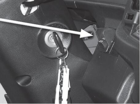
4.Using the Muncie Wire Harness, make the rocker switch connections to the Hino harness in the cab. Push out one of the rocker switch plugs from the area next to the steering wheel. Feed the wire harness behind the dash to this hole and connect the rocker switch. Push the switch into position.
Location of 5 WIRE Frame and 1-WIRE Frame Connectors
5-WIRE and 1-WIRE Conncetions
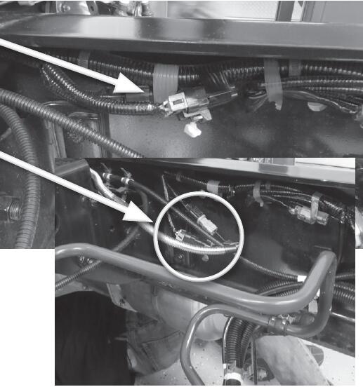
5.Using the Frame half of the harness with the loom, locate the Hino connector along the right side frame rail behind the cab. Remove the blank plug and connect the Muncie Harness.
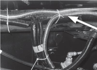
6.Route the loomed harness toward the front of the vehicle and make the connections to the Muncie PTO activation solenoid and the pressure switch.
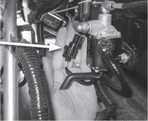
7.Near the PTO is a Hino 2-wire connector for connection to the Allison transmission control and vehicle control. Make this 2-wire connection and cable tie the PTO harness so that it is contained to the vehicle and away from any rotating component or heat source.
8.Check transmission oil level and fill with manufacturer’s approved fluid, if necessary and run engine for 5 to 10 minutes to check for leaks, always staying clear of rotating components.
9.Complete installation by placing warning labels as indicted on borders of the decals. Placement examples are illustrated on page 5; turn to Section 4 of Operator’s Manual.
After complete installation, installers need to check for leaks and proper mounting/ torque of fasteners. Operate the equipment for an appropriate amount of time to establish proper operation or per the equipment manufacturer’s recommendation. After shutting down equipment and engine, check for leaks. Allow unit to set for 60 minutes, then check again for any leaks. Fix all leaks per manufacturer’s recommendation.