Here is an instruction show you guide on how to remove and install electronic unit injector for Perkins 2506-15 industrial engine.
Preparations:
Perkins EST 2024A & 2023A & 2019A Software Free Download
Perkins SPI2 2018A EPC+Service Manual Free Download
Procedures:
Removal
1.Turn the fuel supply to the OFF position.
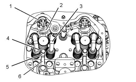
2.Disconnect harness assembly (1) from electronic unit injector (2).
3.Remove valve bridges (3).
NOTICE
If the injector hold down bolt is loose during the removal procedure, inspect the injector bore for wear and debris. Replace the clamp and spacer.
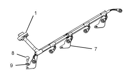
4.Remove bolts (8) and washers (9). Remove harness assembly (1) and support bracket (7) as a unit.
5.Remove bolt (4) and spacer (5).
6.Place an identification mark on electronic unit injector (2) for installation purposes. Each electronic unit injector must be reinstalled in the original location in the cylinder head.
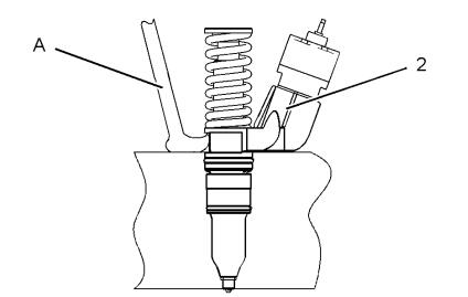
7.Use Tooling (A) to pry beneath the base and free electronic unit injector (2).
8.Remove electronic unit injector (2) and clamp (6) from the cylinder head.
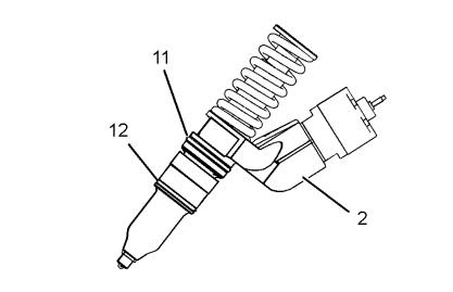
9.Remove O-ring seals (11) and (12) from electronic unit injector (2).
Installation:
NOTICE
Keep all parts clean from contaminants.
Contaminants may cause rapid wear and shortened component life.
1.Use Tooling (D) to clean the carbon deposit from the inside of the electronic unit injector sleeve.
2.Use Tooling (B) to remove the fuel and oil from the cylinder. Evacuate as much fuel and oil as possible from the cylinder before installing the electronic unit injector. Several evacuations may
be necessary.
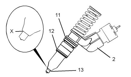
3.Ensure that seat area (X) on the electronic unit injector is clean and free carbon.
4.Install new O-ring seals (11) and (12) on the electronic unit injector. Lubricate the O-ring seals with clean engine oil.
5.Install a new O-ring seal (13) on the electronic unit injector.
Note: O-ring seal (13) should be installed dry.
NOTICE
If a replacement electronic unit injector is installed, the calibration code must be programmed into the electronic control module.
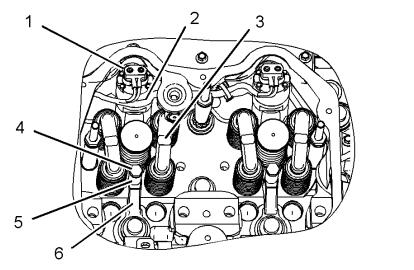
6.Install clamp (6) to electronic unit injector (2).
Install electronic unit injector (2) into the original location in the cylinder head.
7.Install spacer (5) and bolt (4). Tighten bolt (4) to a torque of 55 N·m (41 lb ft).
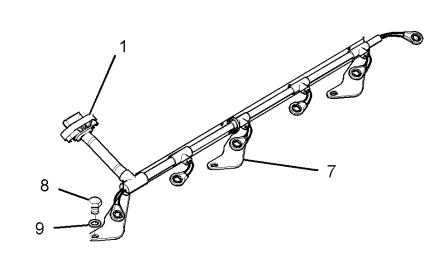
8.Install harness assembly (1) and support bracket (7) as a unit. Install bolts (8) and washers (9).
Tighten bolts (8) to a torque of 105 N·m (77 lb ft).
9.Connect harness assembly (1) to electronic unit injector (2). Use Tooling (E) to tighten the nuts to a torque of 2.5 N·m (22 lb in).
10.Install bridge assemblies (3) in the respective locations.
Note: Ensure that used valve bridges are reinstalled in the original location and the original orientation.
Do not interchange the location or the orientation of used valve bridges.
11.Install the rocker arms and the rocker arm shaft.
12.Turn the fuel supply to the “ON” position.
13.Remove the air from the fuel system.
More trouble repair case for Perkins,pls refer to:Perkins Trouble Repair