The timing of these pumps is normally done by the integral timing marks in the governor housing, as shown in the Workshop Manual. However, if the timing marks are correctly aligned and the engine performance is still not correct, the pump timing can be checked by the spill timing method given below.
Related Contents:
Perkins EST 2024A & 2023A & 2019A Software Free Download
Perkins SPI2 2018A EPC+Service Manual Free Download
Equipment
A spare high pressure outlet from a Bosch pump with the bore drilled to 3 mm diameter.
A “swan neck” spill pipe made from a spare high pressure fuel pipe of the type used with a Bosch in-line pump.
A small container and pipe (with an on/off cock) to give a gravity feed of fuel to the pump inlet connection.
A dial test indicator (DTI) with a magnetic base.
Timing procedure
1 Disconnect the engine speed and stop controls at the pump.
2 Remove the front two rocker covers. Turn the crankshaft in the normal direction of rotation
(clockwise from the front) until the inlet valve of number 4 cylinder has just opened and the exhaust valve is nearly closed.
3 Release a valve of number 1 cylinder to rest on the top of the piston. Fit a suitable collar to the top of the valve stem to hold the valve if the crankshaft is turned too far.
4 Put the DTI in position on top of the valve. Turn the crankshaft to find accurate T.D.C. and set the dial to zero.
5 Remove the number 1 outlet from the pump and remove the peg, spring and delivery valve. Fit the spare outlet to the pump and fit the spill pipe.
Note: Do not interfere with the two nuts fitted either side of the pump outlet as this can alter the phase setting of the pump.
6 Connect the container to the pump inlet to give a gravity feed of fuel of at least 200 mm (8 in).
7 Ensure that the speed control lever is in the minimum speed position and that the stop lever is in the run position. Move the stop lever to the stop position and then to the run position. This is to ensure that the start retard is not engaged.
8 Turn the crankshaft one eighth of a turn (45°) counter-clockwise from the front. Turn on the gravity fuel supply and there should be a continuous flow from the spill pipe.
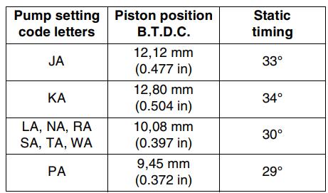
9 Turn the crankshaft slowly clockwise, from the front, until the fuel flow from the spill pipe changes to a fast drip and then ceases. At this point, the piston position B.T.D.C., as indicated by the DTI, should be as shown below:
10 If the timing needs adjustment, remove the tachometer adaptor plate or the cover plate for the
pump gear. Slacken the gear capscrews and turn the pump shaft to the correct position by means of the capscrews. With the pump shaft in the correct position and the gear held against backlash (counter-clockwise from the front), tighten the gear capscrews to 50 Nm (37 lbf ft) 5,1 kgf m. Ensure that the DTI zero is still correct and check the timing again.
11 When the timing is correct, remove the fuel supply,spill pipe and outlet connection. Fit the delivery valve,spring and peg to number 1 outlet. Fit the original outlet connection complete with a new O-ring (Bosch supply) and tighten the connection to 60 Nm (44 lbf ft) 6,1 kgf m.
12 Fit the valve springs and rocker lever to number 1 cylinder and set the valve tip clearance.
13 Fit the rocker covers and, if necessary, the gear cover plate or tachometer adaptor plate.
14 Connect the fuel pipes and bleed the pump.
Connect the fuel pump controls.
More trouble repair case for Perkins,pls refer to:Perkins Trouble Repair