This instruction show you guide on how to remove and install turbocharger for Perkins 400A and 400D industrial engines.
Related Contents:
Perkins EST 2024A & 2023A & 2019A Software Free Download
Perkins SPI2 2018A EPC+Service Manual Free Download
Removal procedure
NOTICE:Care must be taken to ensure that fluids are contained during performance of inspection, maintenance,testing, adjusting and repair of the product.
Be prepared to collect the fluid with suitable containers before opening any compartment or disassembling any component containing fluids.
Dispose of all fluids according to local regulations and mandates.
Keep all parts clean from contaminants.
Contaminants may cause rapid wear and shortened component life.
Note: Plug and cap all open ports and tube assemblies.
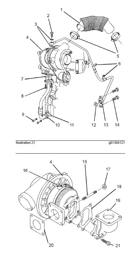
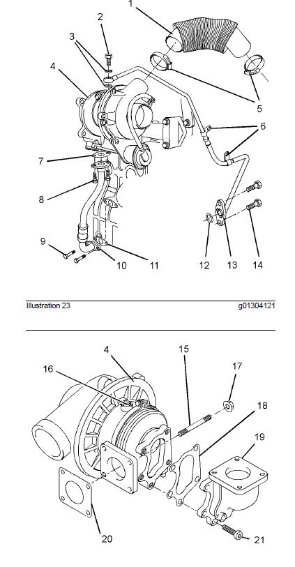
1.Loosen hose clamps (5) and remove air inlet hose (1).
2.Remove allen head screws (21) and remove exhaust elbow (19) from turbocharger (4). Remove gasket (18) from the turbocharger.
3.Remove banjo bolt (2) and washers (3). Remove the fasteners and the spacers (not shown) for tube clips (6). Remove bolts (14) and remove tube assembly (13) from the cylinder block. Remove Oring seal (12).
4.Remove bolts (8) and disconnect tube assembly (10) from the turbocharger. Remove joint (7). If necessary, remove bolts (9) and remove tube assembly (10) from the cylinder block. Remove joint (11).
5.Remove nuts (17) and remove turbocharger (4) from the exhaust manifold. Remove gasket (20) from the exhaust manifold. If necessary, remove studs (15) from the exhaust manifold.
Note: Do not use the actuator rod of the wastegate to lift the turbocharger.
Installation procedure
NOTICE
Keep all parts clean from contaminants.Contaminants may cause rapid wear and shortened
component life.
1Ensure that the turbocharger is clean and free from damage. Inspect the turbocharger for wear. If the turbocharger is worn, the complete turbocharger must be replaced.
2.Test the actuator for correct operation.If the actuator is damaged or the actuator does not operate within the specified limits, the complete turbocharger must be replaced.
3.Clean the mating surfaces of the exhaust manifold.If necessary, install studs (15) to the exhaust manifold. Tighten the studs to a torque of 18 N·m (13 lb ft). Install a new gasket (20) over the studs.
4.Position turbocharger (4) onto the exhaust manifold. Install nuts (17) and tighten to a torque of 25 N·m (18 lb ft).
Note: Do not use the actuator rod of the wastegate to lift the turbocharger .
5.Ensure that tube assemblies (10) and (13) are clean and free from damage. If necessary, replace the tube assemblies.
6.If necessary, position a new joint (11) and tube assembly (10) onto the cylinder block. Install bolts (9). Tighten the bolts finger tight.
Position a new joint (7) on tube assembly (10).
Align tube assembly (10) to the bottom of the turbocharger. Install bolts (8). Tighten the bolts finger tight.Tighten bolts (8) and (9) to a torque of 10 N·m (89 lb in).
7.Lubricate the bearings of turbocharger (4) with clean engine oil through oil inlet port (16). Rotate the shaft of the turbocharger in order to distribute the lubricant.
8.Install a new O-ring seal (12) to tube assembly (13). Position tube assembly (13) against the cylinder block. Install bolts (14). Tighten the bolts to a torque of 10 N·m (89 lb in).
9.Install new washers (3) and banjo bolt (2) to tube assembly (13). Position tube assembly (13) onto turbocharger (4). Tighten the banjo bolt finger tight.
10.If necessary, install the spacer and install the fasteners (not shown) to tube clips (6). Torque the fasteners to 10 N·m (89 lb in).
11.Tighten banjo bolt (2) to a torque of 18 N·m (13 lb ft).
Note: Ensure that the tube assembly does not come into contact with any other components.
12.Clean the mating surfaces of exhaust elbow (19).
Position a new gasket (18) and exhaust elbow (19) on turbocharger (4). Install allen head screws (21).Tighten the bolts to a torque of 32 N·m (24 lb ft).
13.Ensure that inlet hose (1) is clean and free from defects or restrictions. Loosely install hose clamps (5) to air inlet hose (1). Install the air inlet hose to the connection of the inlet manifold (not shown) and to the turbocharger. Tighten the hose clamps.
More Perkins case,please refer to:Perkins Engine Trouble Repair