This instruction show you guide on how to remove and install cylinder head for Komatsu excavator.For more Komatsu case,please refer to:Komatsu trouble repair.
All workshop manuals and parts you can get it here:
Komatsu CSS Full Set 2018 2014 Parts Viwer Free Download
Remove and Install Front Oil Seal for Komatsu PC130-8 Excavator
Removal
Disconnect the cable from the negative (–) terminal of the battery.
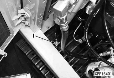
1.Open fuel drain valve (1) and drain the fuel.
After starting draining the fuel, open the fuel filler cap.
Fuel tank: 247l
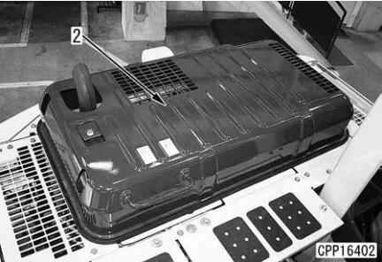
2.Open and lock engine hood (2)
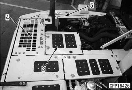
3.Remove covers (3) – (5).
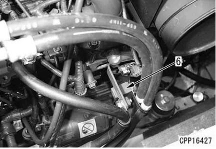
4.Disconnect air conditioner compressor according to the following procedure.
Disconnect air conditioner hose clamp (6).
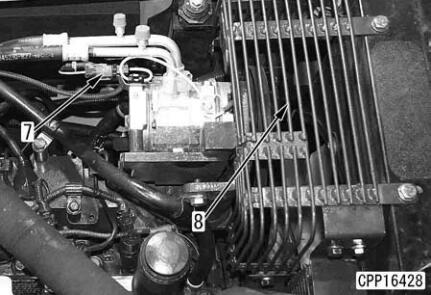
Disconnect wiring connector AC02 (7).
Remove air conditioner compressor drive belt protective cover (8).
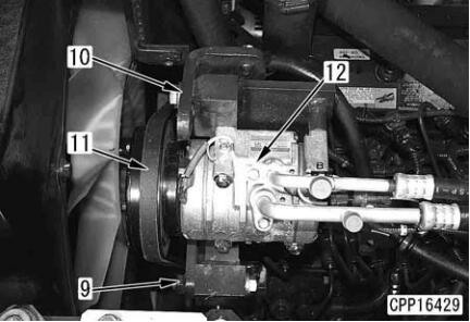
Loosen air conditioner compressor mounting bolt (9) and drive belt adjustment bolt (10) and remove drive belt (11).
Remove air conditioner compressor mounting bolt (9) and air conditioner compressor belt tension adjustment bolt (10) and disconnect air conditioner compressor assembly (12).
Move the air conditioner compressor assembly aside and bind it with a rope, etc. so that it will not be an obstacle.
5.Remove the muffler assembly according to the following procedure.
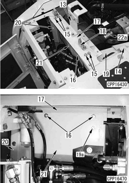
Remove bracket assembly (13).
Remove bracket (14).
Remove 4 upper mounting bolts (15) and 2 partition plate mounting bolts (16) andremove frame (17) and bracket (18) together.
Remove side covers (19) and (20).
Remove mounting bolt (19a) of side cover (19), too.
Remove partition plate (21).
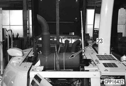
Remove clamp (22a) between the turbocharger and muffler.
Remove 4 muffler assembly bracket mounting bolts (22)
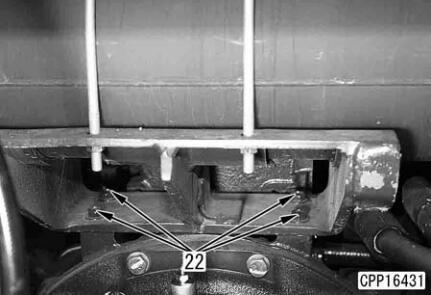
Lift off muffler assembly (23) and bracket together.
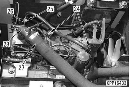
6.Disconnect heater hose clamps (24) and (25).
Disconnect clamp (25) and bracket (26) together.
7.Disconnect air hose (27) from air intake connector (28). [*3]
Make marks at the hose end and tube so that it can be reconnected correctly.
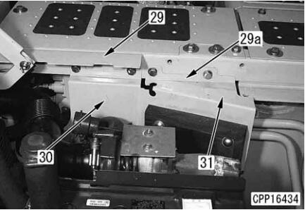
8.Remove brackets (29) and (29a) and partition plates (30) and (31)
9.Remove the turbocharger assembly according to the following procedure.
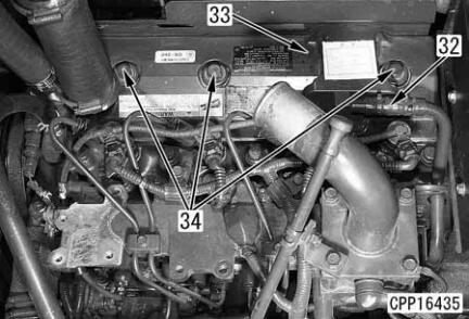
Disconnect blow-by hose (32) from cylinder head cover (33).
Remove 3 nuts (34) and cylinder head cover (33). [*4]
When removing nut (34), take care that the packing sticking to the head cover will not fall.
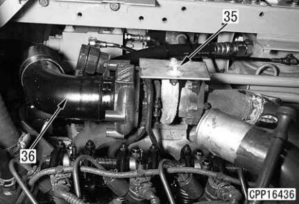
Remove protective cover (35).
Disconnect connector (36) between the turbocharger and air cleaner from the turbocharger.
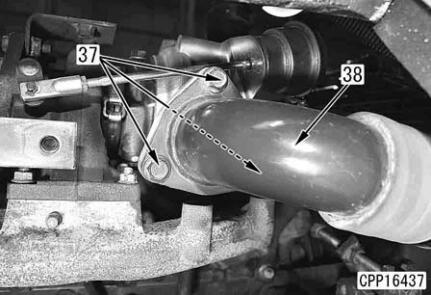
Remove 3 mounting bolts (37) and disconnect air connector (38) from the turbocharger.
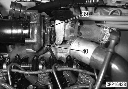
Disconnect turbocharger lubrication inlet tube (39) from the turbocharger. [*7]
Disconnect turbocharger lubrication return tube (40) from the turbocharger.
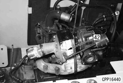
Remove 6 inside mounting bolts, leaving 2 exhaust manifold mounting bolts (41) on the right and left sides. [*8]
Sling turbocharger and exhaust manifold assembly (42) and remove remaining 2 mounting bolts (41).
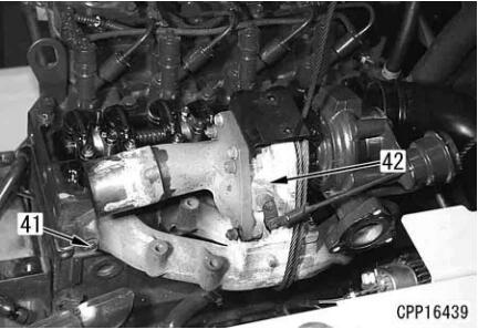
Lift off turbocharger and exhaust manifold assembly (42).
Turbocharger and exhaust manifold assembly: 15 kg
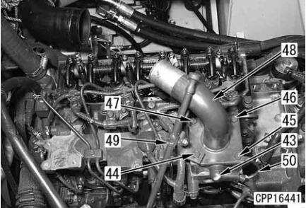
10.Remove the air intake connector and electrical intake air heater according to the following procedure. [*9]
Disconnect electrical intake air heater cable (43).
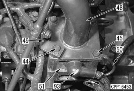
Remove 4 mounting bolts (44) – (47) and air intake connector (48).
Since oil level gauge (49) is also tightened with bolt (44), bind the disconnected oil level gauge with a string,etc. so that it will not be an obstacle.
Ground cable (50) is also tightened with bolt (45).
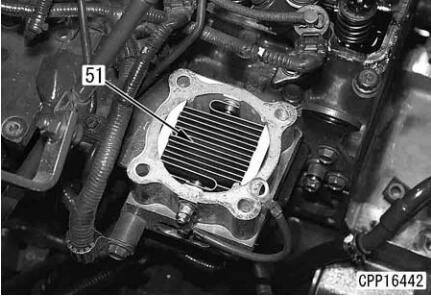
Remove electrical intake air heaterassembly (51).
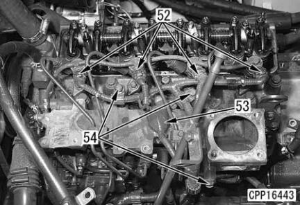
11.Disconnect injector wiring connectors CN1 –CN4 (52) and boost pressure sensor connector
PTIM (53).
12.Disconnect 3 wiring clamps (54).
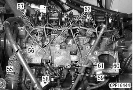
13.Remove the high-pressure pipe according to the following procedure.
Disconnect coolant temperature sensor wiring clamp (55).
Remove spill hose mounting pin (56) and disconnect spill hose (57).
Remove 2 high-pressure pipe clamps (58).
Remove 8 boots (59) from injector (60) and common rail (61). [*10]
Loosen the sleeve nuts and remove 4 high-pressure pipes (62). [*11]
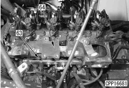
14.Remove 8 air intake manifold mounting bolts (63) and air intake manifold (64).
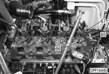
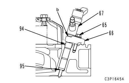
15.Remove the injector assembly according to the following procedure. [*13]
Remove 4 injector mounting bolts (65) and 4 holders (66).
Remove injector assembly (67).
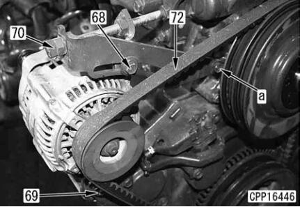
16.Remove the water pump according to the following procedure.
Loosen alternator mounting bolts (68) and (69).
Loosen locknut (70) of the alternator belt tension adjustment bolt and fully loosen alternator belt tension adjustment bolt (71) until the alternator belt can be removed.
Remove alternator belt (72). [*14]
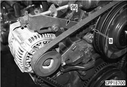
Bolt (a) is tightening the water pump.
Remove it when removing the water pump.
Disconnect coolant temperature sensor TWTR (73).
Disconnect radiator upper hose (74),heater hoses (75) and (76), and radiator lower hose (77) from the water pump.
Heater hose (76) and radiator lower hose (77) are removed together.
Remove fan guard (78).
Remove 6 fan pulley mounting bolts (79).
Remove fan and pulley assembly (80).
Place fan and pulley assembly (80) down.
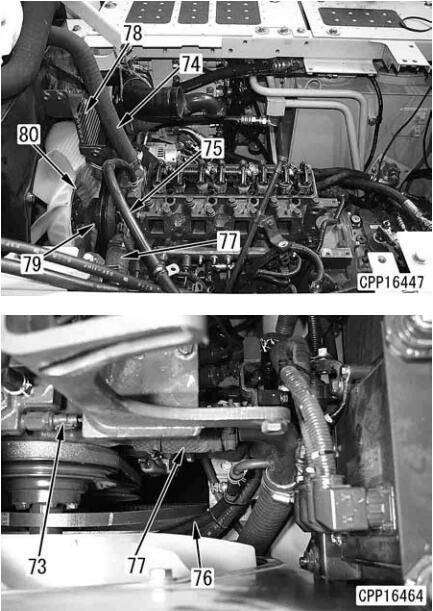
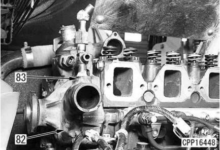
Remove 4 water pump mounting bolts (82).
Among mounting bolts (82), one (a) is tightening the alternator mounting bracket, too. (See the figure in step 3.)
Remove water pump (83).
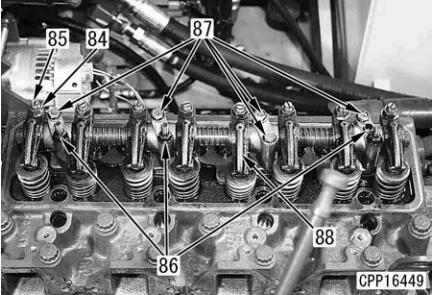
17.Remove the rocker arm assembly according to the following procedure.
Loosen locknut (84) and fully loosen adjustment screw (85).
Loosen the intake and exhaust adjustment screws of all the cylinders.
Remove 3 mounting bolts (86) and 5 mounting bolts (87) and remove rocker arm assembly (88).
Record the locations of mounting bolts (86).
18.Remove the cylinder head assembly according to the following procedure.
Pull out 8 push rods (89).
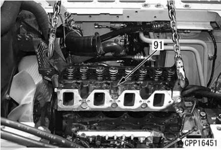
Remove 17 cylinder head mounting bolts (90).
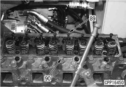
Lift off cylinder head (91).
Cylinder head assembly: 30 kg
Installation
Carry out installation in the reverse order to removal.
For adjustment of the air conditioner compressor belt tension, see “Testing and adjusting air
conditioner compressor belt tension”.
Install the clamp mounting bolts between the turbocharger and muffler according to the following procedure.
Clamp mounting bolt:
1st time: 39.2 – 49 Nm {4 – 5 kgm}
2nd time:68.6 – 122.5 Nm {7 – 12.5 kgm}
Use a new MIKALOR clamp.
Align the hose to the original position (marking position).
Reference
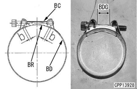
Depth of insertion: 80 mm (aftercooler side) a Set the bridge (BR) under the clamp bolt and
lap it over band (BD) at least (b) reaches 5 mm.
Do not use an impact wrench, when tighten the clamp.
Clamp bolt (BC): Lubricanting oil (THREEBOND PANDO 18B)
When reusing the hose
Install the clamp to the clamp mark made on the hose.
3 Tighten to torque of at least 6 Nm {0.6kgm}
When using a new hose
Tighten until dimention (BDG) is 0 – 3 mm.
When installing the head cover, observe the following precautions.
Fit the O-ring to the head cover.
When installing the head cover mounting nuts and washers, check that the packing is fitted to the head cover.
Check that the packing is free of damage.
Cylinder head cover mounting nut:7.84 – 9.8 Nm {0.8 – 1.0 kgm}
Air hose clamp bolt:
10.5 ± 0.5 Nm {107 ± 5 kgm} [*6]
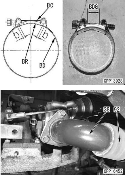
If air hose (92) was disconnected from air connector (38), install the MIKALOR clamp according to the following procedure.
Use a new MIKALOR clamp.
Align the hose to the original position (marking position).
Reference
Depth of insertion: 65 mm (aftercooler side)
Set the bridge (BR) under the clamp bolt and lap it over band (BD) at least (b) reaches 5 mm.
Do not use an impact wrench, when tighten the clamp.
Clamp bolt (BC): Lubricanting oil (THREE-BOND PANDO 18B)
When reusing the hose a Install the clamp to the clamp mark made on the hose.
Tighten to torque of at least 6 Nm {0.6kgm}
When using a new hose Tighten until dimention (BDG) is 0 – 3 mm
Lubrication inlet hose mounting nut:9.8 – 12.7 Nm {1.0 – 1.3 kgm}
Installation procedure for exhaust manifold
Install the guide bolts to the cylinder head and set the gasket.
Set the gasket with the side of stamp of “6205” on the manifold side.
Install the exhaust manifold and tighten the mounting bolts.
Exhaust manifold mounting bolt:
34.3 – 53.9 Nm {3.5 – 5.5 kgm}
When installing air intake connector (48) and electrical intake air heater assembly (45),
observe the following precautions.
When installing air intake connector (48) and electrical intake air heater (51), replace the gasket with new one.
When installing air intake connector mounting bolt (44), tighten oil level gauge (49), too.
When installing air intake connector mounting bolt (45), tighten ground cable (50), too.
If ground cable (50) was removed from electrical intake air heater (51), install it to electrical intake air heater (51) by tightening ground cable mounting bolt (93) to the following torque.
Ground cable mounting bolt:
4.9 – 5.9 Nm {0.5 – 0.6 kgm}
After installing the high-pressure pipe, be sure to install the boot to the sleeve nut.
Direct the slits of the boot out and down.
The boot is installed so that fuel will not spout over the hot parts of the engine and catch fire when it leaks for some reason.
Precautions for installing high-pressure pipe
Do not bend the high-pressure pipe to collect before installing.
Be sure to use the genuine high-pressure pipe clamps and observe the tightening torque.
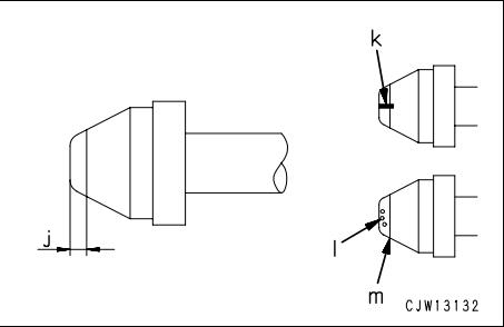
Before installing the high-pressure pipe, check it for the following defects. If there is any of
these defects, it can cause fuel leakage.
Accordingly, replace the high-pressure pipe.
Check the taper seal of the connecting part (Part (j): Part of 2 mm from the end) for visible lengthwise slit (k) and dent (l).
Check part (m) (End of the taper seal: Part at 2 mm from the end) for stepped-type wear (fatigue) which your nail can feel.
Sleeve nut:
25.5 – 29.4 Nm {2.6 – 3.0 kgm}
Before installing the air intake manifold, apply gasket sealant to it.
Apply gasket sealant in a string of about 1 mm in diameter.
Mounting face: Gasket sealant (LG-7)
Installation procedure for injector
Install seal (94) to injector (67).
Install copper gasket (95) to injector (67).
Insert injector (67) in the cylinder head.
Install holder (66) to injector (67).
Tighten holder (66) with injector mounting bolt (65).
Check that holder (66) is installed securely to groove (b) of injector (67) and then tighten the bolt.
Holder mounting bolt:
27 – 30 Nm {2.8 – 3.1 kgm}
For adjustment of the alternator belt tension,see “Testing and adjusting alternator belt tension”.
Radiator hose clamp bolt:
(Both upper and lower hoses)8.8 ± 0.5 Nm {0.9 ± 0.05 kgm}
Tighten water pump mounting bolt (a) to install alternator mounting bracket (96), too.
Before installing rocker arm assembly (88),loosen locknut (84) and fully loosen adjustment screw (85).
When installing rocker arm assembly (88),check that the adjustment screw ball is fitted in the push rod socket and tighten the mounting bolts alternately.
When installing 3 rocker arm mounting bolts (86), check their locations.
Rocker arm mounting bolts (86), (87):
19.6 – 29.4 Nm {2.0 – 3.0 kgm}
For adjustment of the valve clearance, see
Testing and adjusting, “Adjusting valve clearance”.
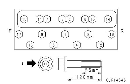
Tightening procedure for cylinder head mounting bolts
Apply molybdenum disulfide lubricant (LM-P) to the threaded parts of the cylinder head mounting bolts and tighten the bolts in the order shown in the figure according to the following procedure.
3 Cylinder head mounting bolt:
1st time: 68.6 ± 9.8 Nm {7.0 ± 1.0 kgm}
2nd time: 107.8 ± 4.9 Nm {11.0 ± 0.5 kgm}
3rd time: Make marks on bolt head and cylinder head and tighten 90 degrees (+30/0 degrees).
After tightening, make 1 punch mark (n) on each bolt head to indicate the number of tightening time.
If there are 5 punch marks on a bolt, do not reuse that bolt but replace it.
p1 denotes a mark on the cylinder head.
p2 denotes a mark on the bolt head.