This instruction show you guide on how to adjust mechanical and hydraulic steering limiters for Grove GMK 3050 crane.
Related Contents:
Grove Crane Full Set Manual Download PDF Download
Grove Crane Full Shop Manual PDF Download
Instructions for the adjustment of the mechanical steering limiters
1.The crane should be completely lowered with the suspension controls and the axle blocking should then be engaged.
2.The crane should then be raised with the outriggers until the wheels are clear of the ground.
3.The mechanical stops should be screwed in (clockwise).
4.Turn the wheel on to a full lock; observe a minimum clearance of 20 mm between the tyre and chassis.
5.With the wheel in this position, adjust the lock stops to maintain the 20-mm minimum clearance.
6.Turn to the opposite lock and repeat steps 4 & 5.
7.Make sure that the steering cylinders have a minimum reserve stroke of 5 mm, once the above adjustments are completed. If necessary, the installation of the cylinders must be corrected to maintain the reserve stroke.
Instructions for the adjustment of the hydraulic steering limiters
1.The straight-ahead position is to be checked before making any other adjustments.
2.The crane is raised as described in 1 & 2 above. The axles must be in the “straight-ahead” position, please be aware of toe-in.
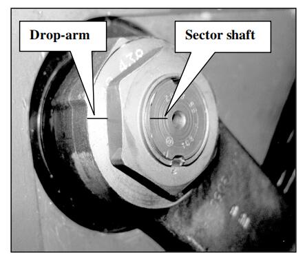
3.Stop the engine and tip the driver’s cab. Check that the drop-arm reference mark is aligned with the corresponding mark on the steering box sector shaft. See drawing 8099 965 402 by ZF. Note: Never apply any external force to remove the drop-arm.
4.Remove the universal joint from the steering box input at the angle drive.You will now see alignment marks on the input shaft, the drive cover and on the outer body of the angle drive housing. These marks should be in alignment. If not adjust the drag link until they do align. Be careful to re-tighten the drag link clamps and make sure they do not foul.
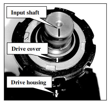
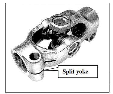
5.Re-fit the universal joint with the split of the yoke in alignment with the reference mark on the angle drive input shaft. The steering must still be perfectly aligned in the straight-ahead position
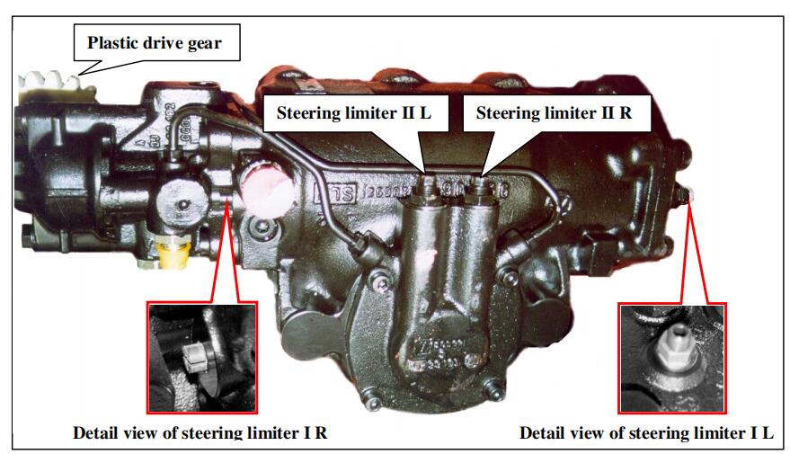
Adjustment of the hydraulic steering pressure limiters
The crane is still on outriggers.
1.Pressure gauges are to be installed in steering circuit 1 & 2. There are pressure test connections at both pumps.
2.Adjusting screws II L and II R are to be screwed fully in (clockwise).
3.Adjustment of the hydraulic steering limiters for “turning left”.
Turn the steering and hold against the mechanical stop. The pressure gauge for circuit 1 should now show at least 120 bar (if necessary the adjusting screw should be screwed out (counter clockwise) until 120 bar is attained). Note: The maximum allowable protrusion of I L is 23 mm.
Adjusting screw I L should then be turned in (clockwise) until the pressure is reduced to 70 bar. The locknut should then be torqued to 70 bar.
Now adjusting screw II L should be turned out (counter clockwise) with increasing pressure until 20 bar is attained. The locknut should then be torqued to 25-35 Nm.
4Adjustment of the steering limiters for “turning to the right”.
Turn the steering to the right and then proceed analogously as the adjustment procedure for turning left.
*First, adjust the setting of circuit I R. Pressure should be set to 70 bar
Then adjust the setting of circuit II R. Pressure should be set to 20 bar and the locknut torqued to 25 – 35 Nm.
*This adjuster is a cross-head device and can only be turned with a screwdriver, there is no lock nut.