This instruction show you guide on how to remove and install crankcase for MTU 12-16V 4000 series engine.
Related Contents:
2022 MTU DiaSys 2.74 2.72 Engine Diagnostic Software Free Download
MTU Diagnostic Tool USB-to-CAN
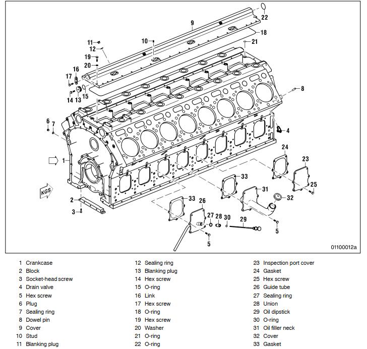
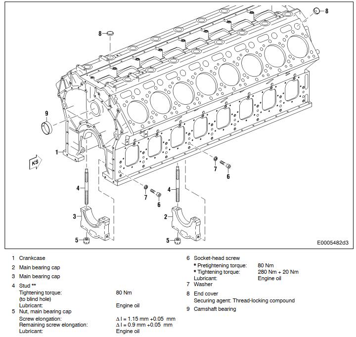
Overview drawings, also applies to 12V
Cover (main oil gallery), guide tube, oil filler neck
Crankcase Removal:
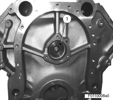
Removing cover (main oil gallery), guide tube, oil filler neck, inspection port cover
Remove cover, guide tube, oil filler neck and inspection port cover as shown in the overview drawing.
Remove blanking plugs, gaskets, sealing rings and O-rings.
Remove O-ring from blanking plug.
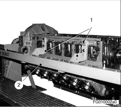
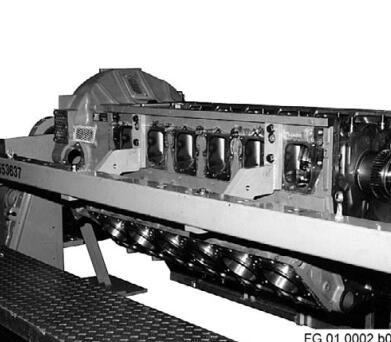
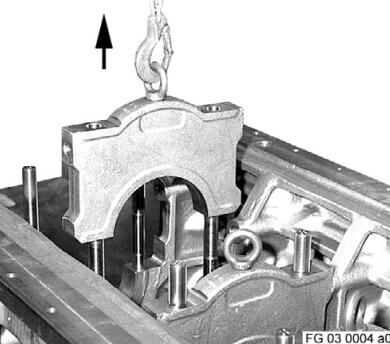
Installing crankcase in assembly dolly
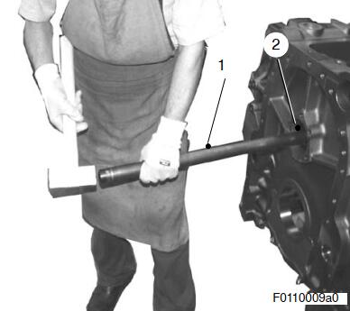
Install supports (1) for assembly dolly at left and right side of the crankcase
Raise crankcase with lifting appliance and lifting ropes, place in assembly dolly (2) and secure.
Disassembly
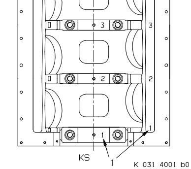
Checking marking on crankshaft bearing cap
Check marking on crankshaft bearing cap to crankshaft, and if necessary mark according to sequence.
To do this, punch the main bearing serial number on crankcase and crankshaft bearing
cap on left side of engine (A side).
Numeral punch 6 mm high.MTU Engine USB to CAN diagnostic adapter
Number sequence: Beginning at driving end side with main bearing No. 1.
Note: In the diagram opposite, the crankcase is rotated 180°. Viewed from this angle the A side is on the right.
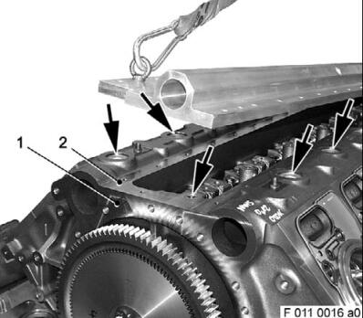
Removing main bearing caps
Remove socket head screws (arrows).
Remove block (1) from crankcase (2).
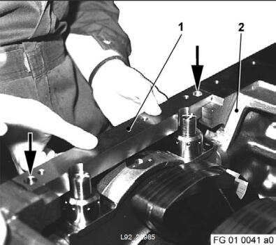
Remove main bearing cap.
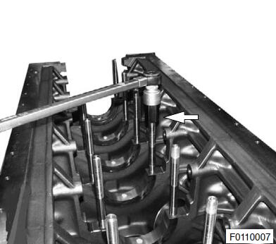
Removing stud(s) for main bearing cap
Important: Only remove studs if necessary.
Remove appropriate stud(s) using an installation/removal tool (arrow).
Removing camshaft bearing bush
Important: Remove camshaft bearing bushes only when wear limit is reached or if damaged.
Remove first bearing bush, driving or free end.
I only one bearing is to be replaced, protect the following bearing against damage
Note: Cover the bottom of the camshaft chamber so that no bearing bush falls into the running gear.
Insert thrust pad (1) into bearing to be removed.
Protect bearings not being removed against damage, e.g. by inserting a rag.
Place removal tool (1) in thrust pad (2) support.
Using a copper hammer, carefully drive camshaft bearing out of crankcase.
Removing next camshaft bearing bush
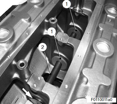
Insert thrust pad (arrow) into next bearing bush which is still installed.
Insert removal tool (2) with guide washers (1) into camshaft bearing bore on crankcase.
Drive out camshaft bearing bush.
Follow same procedure to remove other bearing bushes.
MTU DiaSys 2.73 Diagnostic Software Installation Service
Removing end cover
Important: Remove end cover only if necessary
(e.g. in event of leakages).
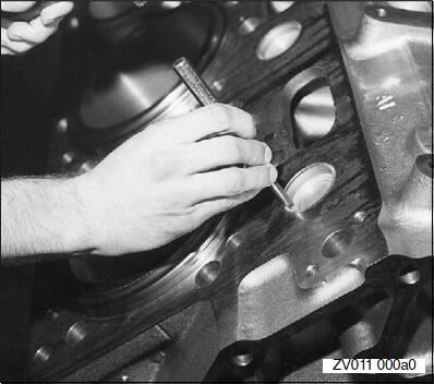
Using a mandrel and hammer, carefully knock the edge of one side of the end cover inwards until it tilts in the bore.Then withdraw the cover with pliers.
When removing, take care that the cover does not fall into the bore and that the sealing face of the bore is not damaged.
Attention: Never attempt to drill a hole in the cover, as chips of metal in the engine cooling jacket can cause localized overheating.
Crankcase Installation
Note: Prior to installation, remove all blanking plugs and covers. Make sure parts are perfectly clean.
Installing inspection port cover, inspection port cover with oil filler neck and oil dipstick
Install and tighten inspection port cover as per overview drawing.
Note: Use new gaskets!
Installing cover (main oil gallery)
Make sure that oil chambers and oilways are perfectly clean.
Complete cover as per overview drawing.
Clean and degrease mating faces on crankcase and cover (2) (arrows).
ÇÇ Insert new O-ring (1) into groove in cover.
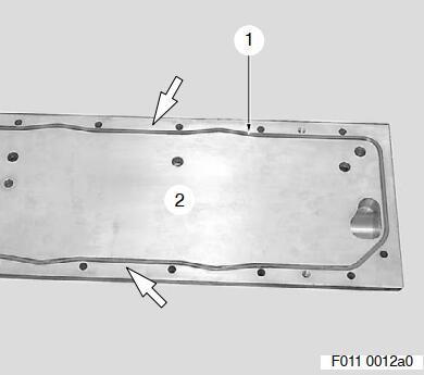
Coat mating face (2) on crankcase with surface sealant (Loctite 5910).
Insert new O-rings (arrows) in oil transfer bores on crankcase.
Insert assembly pins in the crankcase at two diagonally opposite corner points.
Screw in suitable lifting eyes.
Using the lifting appliance, fit the cap onto the assembly pins and slowly lower onto the crankcase support surface.
Install stop plate on face (1) of crankcase.
Align cover with stop plate.
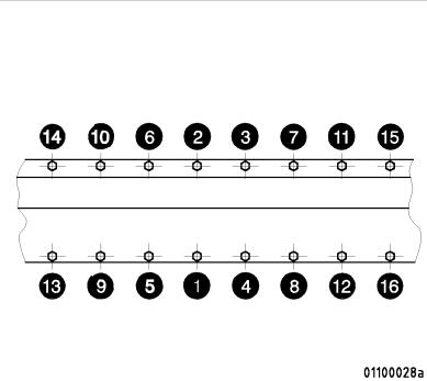
Tighten hex screws as per adjacent tightening diagram.
Removing crankcase from assembly dolly
Move lifting appliance and lifting ropes into position at the crankcase. Ensure lifting ropes are equally tensioned.