This instruction show you guide on how to repair ISUZU F-series P0045 turbocharger boost control solenoid circuit error.
Preparations:
2023 2019 Isuzu G-IDSS Diagnostic Software Free Download (Troubleshooting Guide Included)
ISUZU IDSS Diagnostic Adapter High Quality
DTC P0045 description
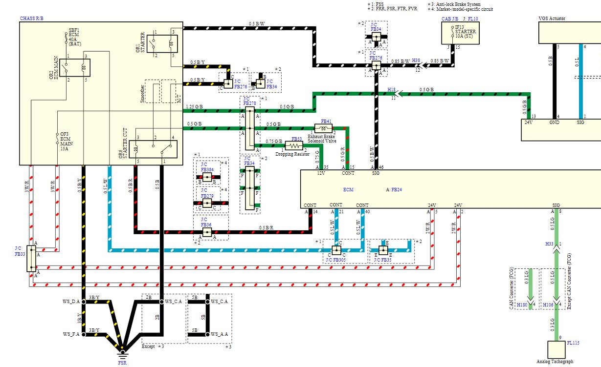
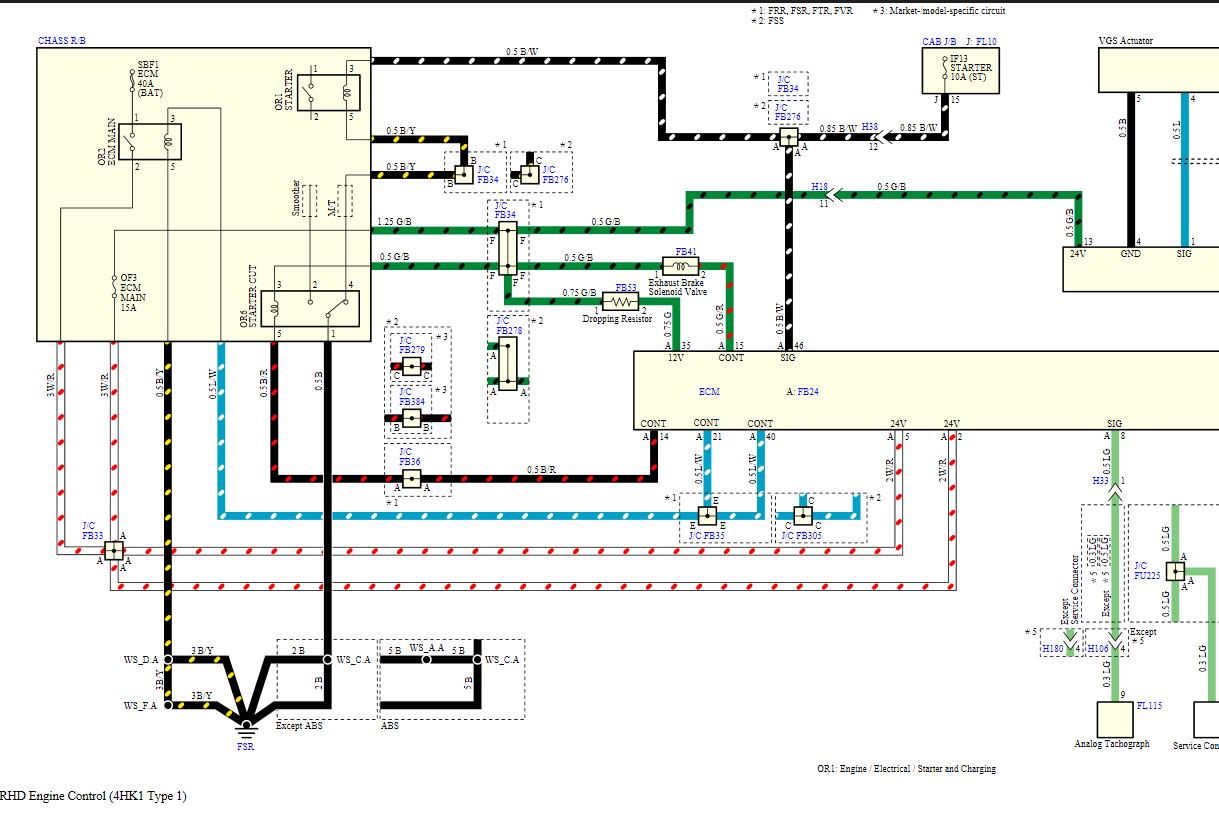
The position of the turbocharger nozzle is controlled by the VGS control unit based on commands from the ECM. The VGS control unit controls the drive signal to the actuator installed to the turbocharger by utilizing position sensor inputs to control the turbocharger nozzles. If no load is applied to the engine, the nozzle is open or there is no boost pressure. When a load is applied to the engine, the VGS control unit controls the motor and closes the turbocharger nozzle. As a result, boost pressure is increased. The ECM controls changes in boost pressure according to the load requirements of the engine. The VGS control unit has the ability to perform internal diagnostics for voltage and signal input and output status. If the VGS control unit detects a nozzle position signal malfunction, motor control signal malfunction, or VGS control unit voltage malfunction, the VGS control unit sends a message to the ECM via the CAN communication circuit and the DTC is set.
Condition for setting DTC P0045
Condition for running the DTC
- The battery voltage is 20 to 32 V.
- The ignition switch is ON.
Condition for setting the DTC
Any of the following are met:
- The VGS control unit detects an excessively high voltage.
- The VGS control unit detects that all position sensor signals are in Low or High condition and have not changed.
- The VGS control unit detects an open circuit, a short to ground, or a short to the power supply circuit in the motor circuit.
- The VGS control unit detects that the motor or nozzle control is stuck.
Action taken when DTC P0045 sets
- The ECM illuminates the check engine warning light. Refer to Action taken when DTC sets – Type A.
- The ECM limits the fuel injection quantity.
- The ECM inhibits the EGR control.
Prioritized DTC check
1) Connect the scan tool.
2) Turn OFF the ignition switch for 30 seconds or more.
3) Start the engine.
4) Observe the DTC information with a scan tool. Is DTC P0563 set at the same time?
Yes
Go to DTC P0563 diagnosis.
No
Repair as necessary
4.VGS motor circuit voltage check
1) Turn OFF the ignition switch for 30 seconds or more.
2) Disconnect the VGS actuator harness connector (E3).
3) Connect a test lamp between the VGS motor circuit (pins 6, 7, and 8 of E3) and the frame ground.
4) Turn ON the ignition switch. Does the test lamp momentarily illuminate then turn OFF?
Note:
- The inspection using a test light should be performed on each circuit.
Yes
=>Go to Inspection for short circuit in VGS motor circuit.
No
=>Go to Inspection for open circuit and short circuit in VGS motor circuit.
5.Inspection for short circuit in VGS motor circuit
1) Inspect the motor circuit between the VGS control unit (pins 10, 11, and 12 of E9) and the VGS actuator (pins 6, 7, and 8 of E3) for a short together. Is the result normal?
Yes
=>Go to VGS position sensor power supply voltage check.
No
Repair the circuit as necessary.
=>Go to Repair verification.
6.Inspection for open circuit and short circuit in VGS motor circuit
1) Inspect the motor circuit in which the test lamp does not illuminate between the VGS control unit (pins 10, 11, and 12 of E9) and the actuator (pins 6, 7, and 8 of E3) for the following. Is the result normal?
- Open circuit
- Short to ground
- Short to the battery power supply circuit or short to the ignition power supply circuit
- Short to position sensor circuit
- High resistance
Yes
=>Go to VGS control unit harness connector inspection.
No
Repair the circuit as necessary.
=>Go to Repair verification.
7.VGS position sensor power supply voltage check
1) Turn ON the ignition switch.
2) Measure the voltage between the VGS position sensor power supply circuit (pin 1 of E3) and the frame ground with a DMM. Is the voltage within the specified range
Yes
=>Go to VGS position sensor signal voltage check.
No
=>Go to Inspection for open circuit and short circuit in VGS position sensor power supply circuit.
8.VGS position sensor signal voltage check
1) Turn ON the ignition switch.
2) Measure the voltage between the VGS position sensor signal circuit (pins 2, 3, and 4 of E3) and the frame ground with a DMM. Is the voltage within the specified range
4.0 to 6.0 V
Yes
=>Go to Inspection for short circuit in VGS position sensor signal circuit.
No
=>Go to Inspection for open circuit and short circuit in VGS position sensor signal circuit.
9 Inspection for short circuit in VGS position sensor signal circuit
1) Inspect the position sensor signal circuit between the VGS control unit (pins 1, 2, and 3 of E9) and the VGS actuator (pins 2, 3, and 4 of E3) for a short circuit. Is the result normal?
Yes
=>Go to VGS position sensor circuit voltage check.
No
Repair the circuit as necessary.
=>Go to Repair verification.
10.VGS position sensor circuit voltage check
1) Turn ON the ignition switch.
2) Measure the voltage between the VGS position sensor power supply circuit and the low reference circuit (pins 1 and 5 of E3) with a DMM. Is the voltage within the specified range?
Yes
=>Go to Actuator harness connector inspection.
No
=>Go to Inspection for open circuit in VGS position sensor low reference circuit.
11.Inspection for open circuit and short circuit in VGS position sensor power supply circuit
1) Inspect the position sensor power supply circuit between the VGS control unit (pin 8 of E9) and the actuator (pin 1 of E3) for the following. Is the result normal?
- Open circuit
- Short to ground
- Short to the low reference circuit
- Short to the battery power supply circuit or short to the ignition power supply circuit
- High resistance
Yes
=>Go to VGS control unit harness connector inspection.
No
Repair the circuit as necessary.
=>Go to Repair verification.
12.Inspection for open circuit and short circuit in VGS position sensor signal circuit
1) Inspect the position sensor signal circuit between the VGS control unit (pins 1, 2, and 3 of E9) and the actuator (pins 2, 3, and 4 of E3) for the following. Is the result normal?
- Open circuit
- Short to ground
- Short to the low reference circuit
- Short to the power supply circuit
- Short to the battery power supply circuit or short to the ignition power supply circuit
- High resistance
Yes
=>Go to VGS control unit harness connector inspection.
No
Repair the circuit as necessary.
=>Go to Repair verification.
13.Inspection for open circuit in VGS position sensor low reference circuit
1) Inspect the position sensor low reference circuit between the VGS control unit (pin 4 of E9) and the actuator (pin 5 of E3) for an open circuit or high resistance. Is the result normal?
Yes
=>Go to VGS control unit harness connector inspection.
No
Repair the circuit as necessary.
=>Go to Repair verification.
14.Actuator harness connector inspection
1) Inspect for poor connections at the VGS actuator harness connector (pins 1, 2, 3, 4, 5, 6, 7, and 8 of E3). Is the connection status normal?
Yes
Replace the turbocharger.
=>Go to Repair verification.
No
Repair the connections as necessary.
=>Go to Repair verification.
15.VGS control unit harness connector inspection
1) Inspect for poor connections at the VGS control unit harness connector (pins 1, 2, 3, 4, 8, 10, 11, and 12 of E9). Is the connection status normal?
Yes
=>Go to VGS control unit replacement.
No
Repair the connections as necessary.
=>Go to Repair verification.
16.VGS control unit replacement
Procedure completion
=>Go to Repair verification.
17.Repair verification
1) Clear the DTC with a scan tool.
2) Turn OFF the ignition switch for 30 seconds or more.
3) Start the engine.
4) Operate the vehicle under the conditions for running the DTC.
5) Observe the DTC information with a scan tool.
More ISUZU repair,please refer to:ISUZU Truck Repair.