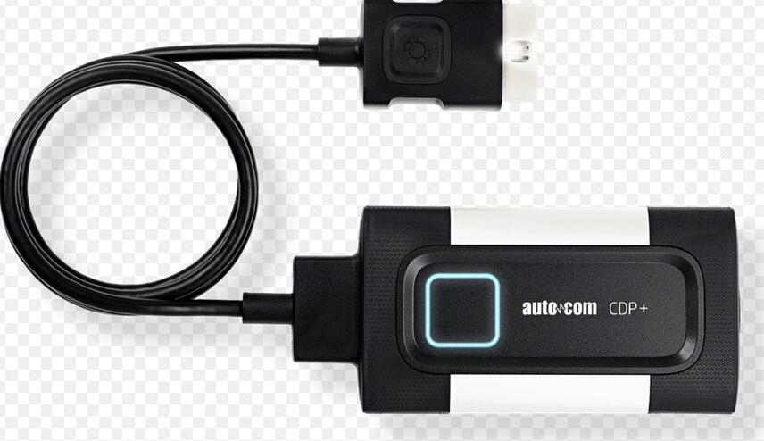
I have some problems with two different types AUTOCOMS CDP+. PCB was different type and both have a problems with message VCI not found. They both using same procesor STM32F205ZGT6 same shematic but different layout. Autocom with 2 PCB (main pcb + relay pcb) is better quality from autocom with only one double layer PCB. The second one has already printed test points to make connections to upgrade firmware.
To repair your broken Autocom with this kind of processor is really easy only you need:
– wires
– solder iron
– Flash_Loader_Demonstrator
– firmware
– some electronic skiils
Procedures:
1.Install Flash_Loader_Demonstrator
2.make wire connection between VDD (pin1 from J400) and pin138 BOOT0 from STM32F20XXX – for Autocom pcb V 3.0 or between TP102 (VDD) and TP206 – for Autocom class B
3.put a switch between pin9 and pin10 from J400 (this connection is needed to join short time NRST to GND – make resset)
4.connect Autocom to car (or external 12v) and USB to computer
5.start Flash_Loader_Demonstrator and dont change anything in settings just select yout VCI port number
6.connection wire is between VDD and BOOT0 (step2) all time while upgrating firmware
7.After Flash_Loader_Demonstrator window is appear then made short connection between pin 9 and pin 10 from J400 (look at pictures)
8.If everything is OK then next window will be avaliable in Flash Loader Demonstrator
9.When connection with MCU is avaliable, you need choose type of MCU 1024K
10.Select your firmware ex. 2012.3.bin from download to device option and global erase
11.Click next and wait about 7 min for uploading your firmware to Autocom
12.After uploading firmware finished just disconect Autocom from OBD2 and USB and connect it again and make test and you will be suprised your Autocom is live again
All files and documentation is here
I hope this post was helpfull for all people having problems with Autocom chinese clones.