WHAT IS MULTIPLEXING?
Multiplexing is the concept of transmitting multiple unique electronic signals over a much smaller number of wires. Vehicular applications of multiplexing technology typically use just two wires for this function.Multiplexing allows these two wires to carry electronic data that can control a variety of electronic equipment.
The number of wires needed to connect components is greatly reduced, which offers better reliability and improved vehicle uptime. Although limited multiplexing had been used previously by Navistar, the introduction of the industry’s first high performance trucks has fully exploited this technology.
COMPONENTS OF THE MULTIPLEXING SYSTEM
The multiplexed electrical system consists of the following standard or optional components:
- Body Controller / Electrical System Controller
- Remote Power Module(s)
- Remote Air Solenoid Module(s)
- Electronic Gauge Cluster
- Switch Packs
- Light Control Module (LCM)
- HVAC Controls
- Engine Controls
- Transmission Controls
- Anti-Lock Brake Module
Body Control Module (BCM)
The Body Control Module (BCM) is a body systems computer used to control many of the vehicle’s electrical functions. It is the heart of the multiplex system. When installed on trucks, all BCMs are located under instrument panel. On bus applications, they are mounted to the underside of the dash.
The BCM receives inputs from driver controls, sensors, and switches providing outputs to vehicle loads,gauges, relays, and remotely mounted modules. Software to control a vehicle’s specific electrical / electronic features and components is programmed into the ESC / BC using a computer and the Diamond Logic® Builder Fleet program.
Navistar has released three different generations of the BCM (Figure 2).
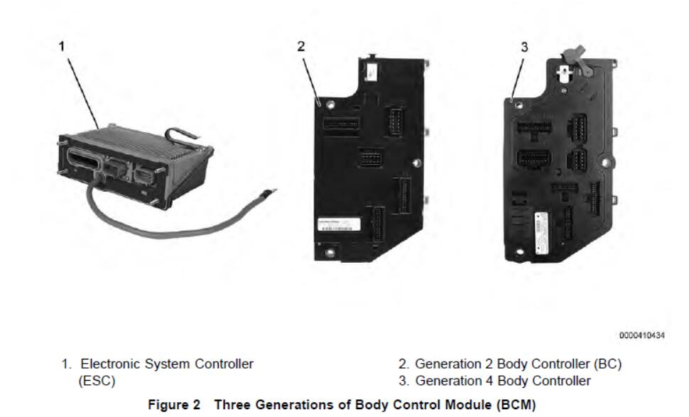
NOTE–The BCM is commonly referred to as the Body Controller, Vehicle Control Module (VCM),Electronic System Controller, as well as the Body Control Module.
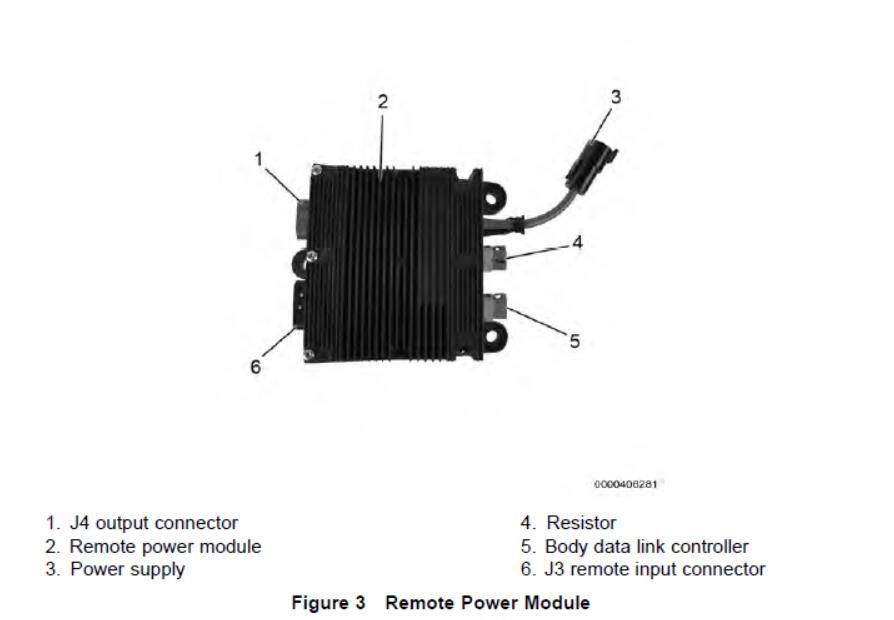
Remote Power Module (RPM)
Remote Power Modules serve as gateways into Navistar’s electrical system. Body Controller / ESCprogramming allows modules to be programmed to control many different types of added body equipment.
The base package for integration includes a module, which contains six 20-amp outputs, for controlling lights or other loads required for a vehicle’s application (up to 80 amps total). Remote power modules may be controlled using pre-engineered features from Navistar or special customer developed features created using Advanced Logic in the Diamond Logic® Builder program. Remote Power Modules also include six inputs that can provide remote switching and feedback capability.
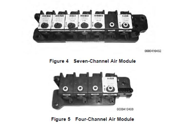
Remote Air Solenoid Module (RASM or MSVA)
Through the development of a family of Remote Air Solenoid Modules, air accessory devices such as horns,PTOs, sliding fifth wheel locks, suspensions, transfer cases, differential locks, power divider locks, auxiliary transmissions, and two-speed axles and more can be controlled by electric in-cab switches. Currently,there are two types of Remote Air Modules, a seven-channel and a four-channel version. Both are factory installed with in-cab switches.
NOTE–The seven-channel module is not available in post 2007 vehicles.
Electronic Gauge Cluster (EGC)
Located in the instrument panel, the Electronic Gauge Cluster includes the instrument gauges, warning indicators, and an LCD digital display, which provide odometer, transmission gear indication, compass heading, and outside temperature displays. The instrument cluster displays the crucial operational functions of the vehicle. The number of gauges and their placement can vary depending on the options selected. Anaudible alarm can be programmed in DLB to sound when certain gauge values read out of range.
The cluster’s gauges are controlled by the ESC / BC via the J1939 Data Link.
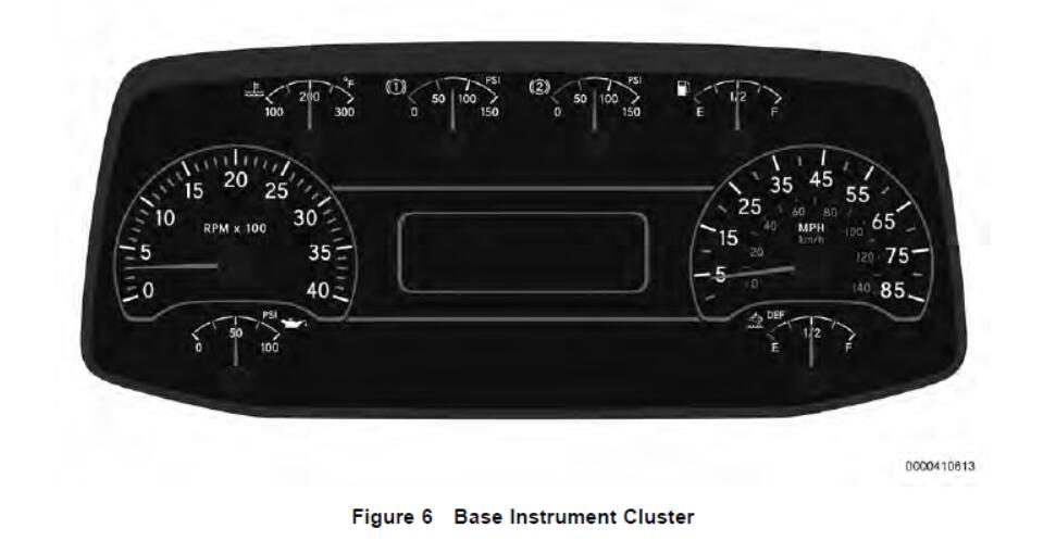
The Base Instrument Cluster displays numerous functions, alerts, and indicators through analog gauges,indicators, and an information LED screen. Depending on the cluster configuration that is selected, there can be 6, 7, or 8 analog gauges in the instrument cluster that provide information to the operator. The Base Instrument Cluster is available on 2017 and later International® vehicles.
An LED screen is located in the middle of the cluster that displays vital information to the operator. A push button, located on the right, is used to scroll through the various menus.
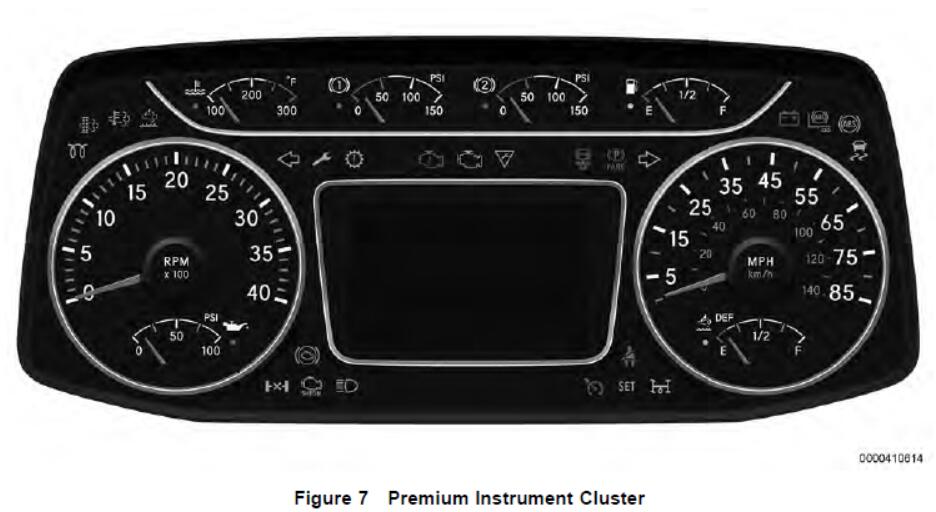
The Premium Instrument Cluster is an upscale version of the EGC that displays numerous functions, alerts,and indicators through analog gauges, indicators, and an information LCD screen. Depending on the cluster configuration that is selected, there can be 6, 7, or 8 analog gauges in the instrument cluster that provide information to the operator.
The Premium Instrument Cluster utilizes a 5 in LCD screen, located between the tachometer and speedometer.
There are various menus that can be navigated through using the Cluster Display Control (CDC) on the instrument panel to the lower right of the Instrument Cluster. A toggle joystick allows the operator to scroll through various menus, and when pressed, a selection is made. The back button, represented by an arrow,can be used to return to previous menus and screens.
Rocker Switch Packs
The Rocker Switch Packs are provided in six and 12-switch modules. Commonly found in the center panel,they are used to control loads such as fog lights, heated mirrors, and Power Take Off (PTO) options. Diamond Logic® Builder software makes it easy to move and relocate switches.
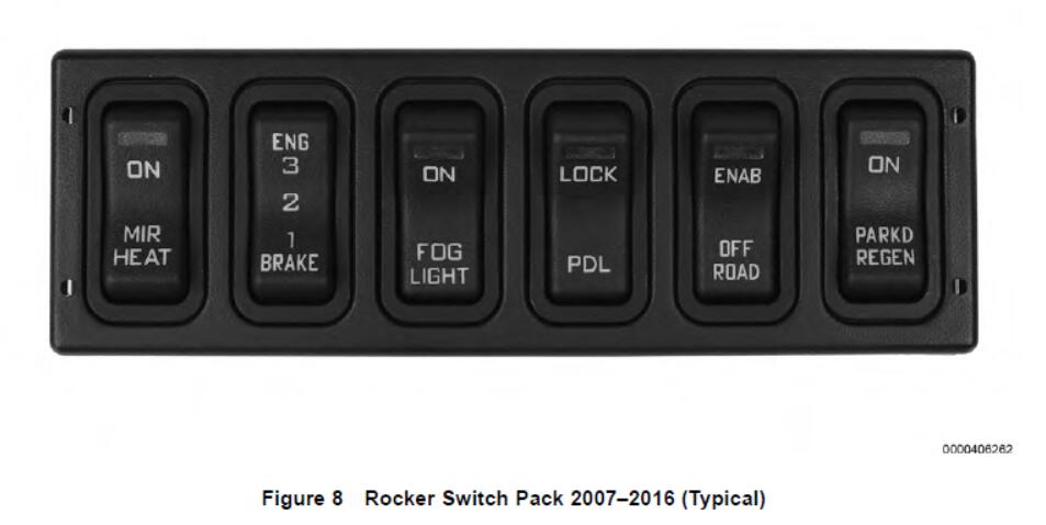
When multiple switch packs are utilized, they are daisy-chained together to eliminate excess wiring. Switch actuators control what signals are sent from the Switch Pack.
On vehicles built between 2007 and 2016, the switch pack communicates on the switch data link. Switch packs on these vehicles have a green Light Emitting Diode (LED) indicator that provides the operator with information on the load and switch status.
On vehicles built in 2017 or later, the Switch Pack(s) communicate on the Human Machine Interface (HMI) data link. These switch packs have an LED indicator with 7 different color options. The color of the LED is dependent on the programmed feature code of the switch or the custom logic that is assigned to the switch.
Light Control Module (LCM)
The Light Control Module (LCM) contains a light multi-switch for the fog lights, headlights, parking lights, and the option for rear fog lights.
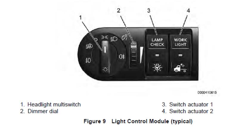
The LCM is located in the dash panel on the left side of the steering wheel. The LCM communicates with the Body Control Module (BCM) over the Low Speed HMI data link. The LCM also contains space for two optional switch actuators.
How to Remove and Install BMW Light Control Module (LCM)
How to Repair BMW Light Control Module (LCM) On E39
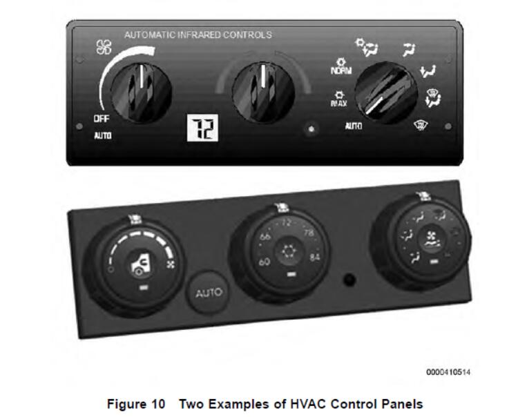
HVAC Controls
An electronic module located in the center of the instrument panel controls the HVAC system. The HVAC controls eliminate complexity by controlling functions such as the air temperature and air outlet selection with electronic motors.
Engine Control System
The engine control module shares engine information such as RPM, vehicle speed, water temperature, and oil temperature with any component connected to the data link that requires the information. The engine also receives commands for cruise control, clutch and brake status, and engine fan control from the ESC / BC.
Electronic Transmission Controls
The transmission controller communicates gear position, transmission oil temperature, and warning light status with the electronic gauge cluster on the drive train J1939 Data Link.
Anti-lock Brake System (ABS)
The Anti-lock Brake System prevents wheel lock-up during vehicle braking events. The system communicates with the ESC / BC and the engine controller to limit engine torque, disable retarders, and control the ABS, ATC and trailer ABS warning lamps in the electronic gauge cluster.