Power Source
Before power up the interface, please read and study the technical specifications, if you didn’t use the UltraProg interface with certified power supply. Every UltraProg interface
is fully tested for all functions before sell to end-users.
Related Contents:
UltraProg Programmer Software Free Download
How to Install UltraProg Programmer Software
UltraProg interface is protected against apply opposite polarity DC voltage and also it has Fast 1000mA 5x20mm glass fuse inside.
After power on the green LED must lit, on the interface, otherwise power voltage is too low, or maybe the unit or fuse is faulty.
Power LED may blinking or switched off temporarily during in operation. This is normal behavior, and not means any fault of the interface.
Description of PC and Power panel
On below pictures please see the pinout:
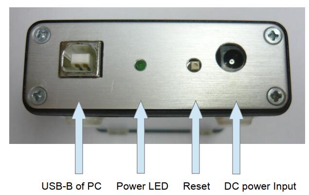
USB-B: Please connect this with USB A-B cable to any free port of your PC
Power LED: This LED lamp must be lit, when unit is powered up. Also during in operation,may blinks, or dark for a short time.
Reset: This is a button to restart your interface, especially when update the firmware DC Power: Apply the DC power in here (center pin is positive)
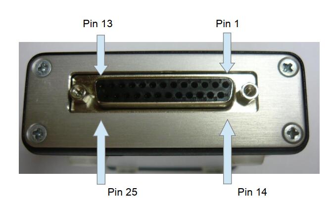
Description of Peripheral Panel
| UltraProg Pin | Description | Direction |
| 1 | RS485 B | I |
| 2 | RS485 A | O |
| 3 | +5V tied with 10k to internal Vcc | O |
| 4 | +5V tied with 10k to internal Vcc | O |
| 5 | GND tied to ground | GND |
| 6 | Not Connected | NC |
| 7 | Reset output for microcontrollers | O |
| 8 | General port TTL level | I/O |
| 9 | General port TTL level | I/O |
| 10 | K-line for diagnostics interface | I/O |
| 11 | +9,1V output | O |
| 12 | +12V output with on/off function | O |
| 13 | Not Connected | NC |
| 14 | +5V output (Common with system) | O |
| 15 | General port TTL level | I/O |
| 16 | General port TTL level | I/O |
| 17 | General port TTL level | I/O |
| 18 | General port TTL level | I/O |
| 19 | General port TTL level | I/O |
| 20 | General port TTL level | I/O |
| 21 | General port TTL level | I/O |
| 22 | General port TTL level | I/O |
| 23 | General port TTL level | I/O |
| 24 | General port TTL level | I/O |
| 25 | GND tied to ground | GND |
Peripheral pins numbering