This instruction show you guide on how to repair Paccar truck databus gauges inoperative DTC148109,DTC148209,DTC148309 and DTC176102 V-CAN (J1939).
Preparations:
Paccar ESA Electronic Service Analyst v5.4.3 v5.2.2 Free Download
Symptom:
One or more of the following gauges inoperative. All other non-V-CAN gauges are operational.
- Engine Oil Pressure Gauge
- Engine Oil Temperature Gauge
- Engine Coolant Temperature Gauge
- Tachometer
- Speedometer
- Diesel Exhaust Fluid Gauge
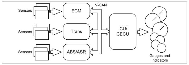
V-CAN Databus gauges receive their data from the J1939 data link via the engine ECU, which receives its data from various sensors on the engine and transmission.
NOTE: In case of a PX-6 engine, the calculated value (instead of measured value) is broadcast by the engine
Procedures:
Step 1:
Turn ignition key ON.
Start ESA, then select “Connect” to establish communication to the vehicle
Step 2:
Select “Monitor”.From the “Components” window, select all of the failed functions then select “Open”
Gauge graphic(s) on screen display reasonable reading Go to Step 3.
Gauge graphic(s) on screen do not display reasonable readings Go to Step 4.
Step 3:
Select “Simulate”.
Drag the “Value” bar until the pointers on the gauge images are approximately mid-scale. Observe vehicle gauge movement.
Vehicle gauge(s) do not move. Go to Step 3-1.
Vehicle gauge reading(s) are in the same range as the ESA gauge image(s). Go to Step 3-7
Perform the following checks:
NOTE:For vehicles with a CECU, use the “Program” feature in ESA to make sure that the parameter for the inoperative gauge is enabled.
An inoperative gauge may simply have its CECU parameter set to disabled.
1.Check CVSG data link wiring: Observe Gauge position in the wiring daisy chain.
a.If gauge is mounted between two other functioning gauges CVSG data link wiring is OK. Go to Step 3-5.
b.If gauge is last gauge in daisy chain or followed by other non-functional gauges, go to Step 3-2.
2.Check continuity between Pin 1 on gauge harness connector and Pin 14 of the 52 Pin ICU/CECU connector C.
3.Check continuity between Pin 3 on gauge harness connector and Pin 15 of the 52 Pin ICU/CECU connector C.
4.Repair daisy chain jumper harness as necessary.
5.Once continuity on both wires exists, perform “Simulate” test again.
a.If gauge functions properly during “Simulate” test, repair is complete.
Return truck to service.
b.If gauge does not function during “Simulate” test, install Test ICU/CECU and perform “Simulate” test again.
i.If gauge functions properly test is complete. Install new ICU/CECU permanently. Re-test and return truck to service.
ii.If gauge does not function properly during “Simulate” test, replace gauge.
6.Once gauge is replaced
a.Verify gauge functionality.
b.Return truck to service.
7.Is this a recheck after Step 4?
a.Yes. Return truck to service
b.No, Gauge and CVSG data link wiring is not the problem. Go to Step 4
Step 4:
Select “Diagnose” to view “Active” diagnostic trouble code
DTC 148309 displayed –ICU/CECU cannot read messages from Engine on V-CA
Indicates the problem could be an open or short in the wiring from the ICU/CECU to the Engine ECU. In addition, J1939 components such as Terminating Resistors may be missing or damaged. Data from the Engine
ECU may be missing or corrupting the J1939 data stream. Go to J1939 Lite
Diagnostic Procedure. Correct faults found in J1939 Diagnostics section and return to Step 2 above
DTC 148109 displayed –ICU/CECU cannot read messages from ABS on V-CA
Indicates the problem could be an open or short in the wiring from the ICU/CECU to the ABS ECU. In addition, J1939 components such as Terminating Resistors may be missing or damaged. Data from the ABS ECU may be missing or corrupting the J1939 data stream. Go to J1939 Lite
Diagnostic Procedure. Correct faults found in J1939 Diagnostics section and return to Step 2 above.
DTC 148209 displayed – ICU/CECU cannot read messages from Transmission on V-CA
Indicates the problem could be an open or short in the wiring from the ICU/CECU to the Transmission ECU. In addition, J1939 components such as Terminating Resistors may be missing or damaged. Data from the Transmission ECU may be missing or corrupting the J1939 data stream. Go to J1939 Lite Diagnostic Procedure. Correct faults found in J1939 Diagnostics section and return to Step 2 above.
Inactive” DTCs or No DTCs displaye
Indicates two possible sets of causes for fault.
1.Indicates the problem could be caused by faulty data from Engine ECU.
a.Connect Engine OE Diagnostic Tool to determine if engine is transmitting engine data when the engine is running.
i.If data from the Engine ECU is not displayed in the OE
Diagnostic Tool check for:
(1) Missing signal from engine mounted sensor or Vehicle Speed sensor.
(a) Faulty sensor
(b) Faulty engine sensor wiring supplied by Engine OE
(c) Faulty vehicle speed sensor wiring on chassis or engine harness
(2) Missing signal from Engine ECU.
(a) Faulty Engine ECU hardware
(b) Faulty Engine ECU software
ii.If data from the Engine ECU is displayed on the OE Diagnostic
Tool:Check to insure Engine data has been transmitted over J1939 circuits as opposed to J1587 circuits. Go to J1939 Diagnostics. Correct faults found in J1939 Diagnostics section and return to Step 2.
-OR Connect test Engine ECU to determine if original ECU has failed. Go to Step 2.
2.Indicates the problem could be intermittent in nature. Proceed with diagnosis of inactive codes while looking for loose connectors, terminals or bare wiring that might make occasional contact with metal parts or other wires. Technicians may need to manipulate connectors to find intermittent connections. Go to J1939 Diagnostics. Correct faults found in J1939 Diagnostics section and return to Step 2 above.