Here are some frequency ask question from Chrysler Diagnostic Application customers,hope it helps!
How to Install Chrysler Diagnostic Application CDA 5.01
Chrysler Diagnostic Application CDA 5.01 4.02 Free Download
Question 1:
Why did the Chrysler Diagnostic Application (CDA) replace the EDT2?
Answer 1:
The CDA is replacing the EDT2 due to a VP-level decision (Dan Knott – VP of Global Service,Bill Mattingly – VP of Core Core EE Engineering, and Bob Lee – VP of Powertrain Engineering)
to establish a “single” comprehensive diagnostic and flash tool application for Chrysler Engineering, Manufacturing, and Service. This was done in order to improve overall EE product
quality, improve service quality and readiness, reduce tool redundancies, and consolidate resources.
Question 2:
What is currently supported by the Chrysler Diagnostic Application?
Answer 2:
The Chrysler Diagnostic Application (CDA) supports the following hardware platforms:
• Vector Hardware (CANcardX, CANcardXL, CANcaseXL, CANcardXLe, CANboardXL)
• StarMOBILE (service tool)
• wiTECH VCI Pod (service tool)
• StarSCAN (up to version E4.02 only)
o E5.01 and forward is NOT supported on StarSCAN
The CDA has the following functionality:
• UDS and KWP2000 based ECU communication
• Functional CAN Messaging
• ECU DTCs
• ECU Flash
• CAN Bus Logging
• Engineering Features
o Read/Write Control
o I/O Control
o Fault Management
o ECU Reset
o ECU Calibration Writer
o Diagnostic Message Control
o Diagnostic Session Control
o Enable/Disable Normal Messaging
o Onboard ECU Routines
o Off Board Routines
o LID/PID Editor
o ECU Configuration
o ECU Security Access
o Read/Write Memory by Address
o Bus Logging
o Direct Bus Access
o Dual CAN channel communication (PowerNet 2011 Configuration)
Question 3:
What are ENG files?
Answer 3:
ENG files are essentially containers for ECU specific data and functionality. ENG files are released according to variant, version, and minor version. The contents of an ENG file are:
• ECU Diagnostic Database
• ECU Text (Strings) File
• Security Unlocks
• Off Board Routines
When any of the above contents needs to be added or updated, a new minor version of the ENG file must be generated and then posted to the Diagnostic Workbench. All diagnostic data
is maintained and released by the Core Vehicle Diagnostics group at Chrysler.No diagnostic data (ENG files) are bundled with the CDA software. The user of the CDA must
import them. ENG files cannot be bundled with the CDA software because new ones are released daily. See the CDA User Guide for instructions on how to import ENG files into the
CDA.
Question 4:
Does the Chrysler Diagnostic Application support Vector hardware (e.g.CANcardX/XL)?
Answer 4:
Yes, support for Vector hardware such as CANcardX, CANcardXL, CANcaseXL, CANcardXLe,and CANboardXL is present in the latest CDA version.
Question 5:
I have installed the latest version of the application. Why don’t I see any ECU or vehicle data?
Answer 5:
The Chrysler Diagnostic Application is deployed without any ECU or vehicle data. ECU and other data required by certain features of the application are available via the Diagnostic
Workbench (specifically eRepository). The following types of data packages must be obtained from the Diagnostic Workbench:
Chrysler Diagnostic Workbench
• ECU diagnostic data files (.eng files : My Workbench > ECU View > select either ECU
View or Vehicle View to obtain appropriate .eng files)
• Gateway Configuration Files (GatewayConfig.bndl: Tools > Software & Drivers)
• ECU Flash Files (.efd files: My Workbench > ECU View > Flash)
Supplier Diagnostic Workbench
• ECU diagnostic data files (.eng files: External Users must contact their Chrysler Core
Release Engineer to obtain the necessary .eng files or ECU Diagnostic Packages that
they require.
• Gateway Configuration Files (GatewayConfig.bndl: eRepository > Gateway
Configuration
• ECU Flash Files (.efd files: eRepository > Flash Files)
These pieces of data must be transferred to the tool by the user using the File Management
features of the application.
Question 6:
How does the CDA handle Off Board Routines?
Answer 6:
An off board routine is a custom script that streamlines a series of functions that need to be performed on an ECU or set of ECUs. CDA version E4.01 and forward will support Off-Board
Routines. Off Board Routines are deployed inside of ENG files. When a routine is ready for release, new min versions of an ENG files are created. Which ENG files are created depends
on what variants and sometimes versions of an ECU the routine is intended to be used on. The new routine is then put inside those ENG files and posted to the Diagnostic Workbench website
where they can then be downloaded and imported into the CDA.
If a new off board routine is needed for engineering use, a request should be entered through the Jira issue tracking system which can be accessed through the Diagnostic Workbench under
Support -> Submit Issue. There is a project dedicated to off board routine requests listed on that page. The request will be reviewed by the CDA Release Planning team and eventually
scheduled for implementation.
Question 7:
How can I change the CAN baud rate?
Answer 7:
All hardware configuration on the CDA can be done immediately when the application launches.
The physical communication channels of your Vector hardware or StarMOBILE/wiTECH tools can be mapped to a bus type, and thus a specific baud rate for that bus. Please click on the
Help button in the upper-right corner for assistance with the device configuration.
Question 8:
How does the StarMOBILE’s vehicle connection system work?
Answer 8:
There are certain conditions that must exist for the StarMOBILE tools to communicate with a vehicle. The first conditions that must be met for the tool to operate properly are that power and grounds must be connected at the Data Link Connector (DLC). This means that pin 16 on the DLC will need to have battery voltage (B+) at all times and that pins 4 and 5 have a “clean” path to ground. When the StarMOBILE is turned on and plugged into the DLC, the light near the power button on the tool will turn green when vehicle power is present. If the tool is running off of its internal battery, then the light will be a solid red. A green light with an occasional red blink means that the tool is running off of the vehicle’s battery and charging its internal battery.
Note:
on boot up, the tool may take a few seconds to recognize that vehicle battery is present. If you don’t see a green light, then check all of your cable connections from the StarMOBILE tool to the DLC. Also check that the vehicle’s battery voltage is at least 10.5 Volts. This is the approximate voltage at which the tool will switch from vehicle power to internal battery power for most of its hardware. Vehicle communications hardware on the StarMOBILE tool would still draw off of vehicle power and function above 6 Volts. If all of these conditions are met and you are still having trouble communicating, then try a different vehicle cable or plug into a different vehicle.
If vehicle battery is present, the StarMOBILE tool will attempt to identify the cable attached to it.
There are different types of cables that can be connected to the tool vehicle connector, so be sure you’re using the correct type.
Question 9:
How can I easily connect the wiTECH VCI Pod or StarMOBILE to ECUs that are not on a vehicle or buck?
Answer 9:
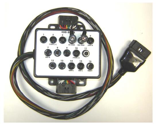
When connecting to ECUs in a desktop setting, the Chrysler Diagnostic Application development team recommends the use of a breakout box. A breakout box provides easy access to all of the lines in the Vehicle On-Board Diagnostic connector. Using standard banana plug connectors, you can easily connect the CAN, power, and ground lines to the appropriate J1962 pins so that the standard vehicle cables can be used.
Breakout Boxes are available from Dearborn Group and may be purchased by contacting their sales department at (248) 488-2080 or [email protected]. The part number is DG-OBDII-BOX.
The Vehicle Diagnostic Connector pin assignments are given in the table below.
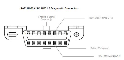
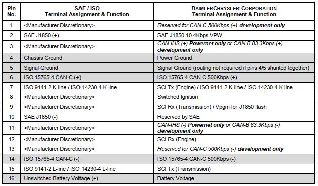
*Note: When using a desktop setup, ensure that the ground lines, on J1962 pins 4 and 5, are tied together for a common ground.
The table above shows that the vehicle’s diagnostic connector has the Diagnostic CAN-C bus available on pins 6 (CAN+) and 14 (CAN-). Since the StarMOBILE device was initially designed for vehicle connection in the service environment, the only CAN-C bus available on these devices on pins 6 and 14 of the vehicle cable. There is no multiplex capability on the StarMOBILE. Therefore, if you are attempting to connect to the CAN-C (pins 1 and 13) bus on a development vehicle, you must route the pins accordingly. A breakout box (described above) provides an easy way to do this.
The wiTECH VCI Pod has two high speed CAN-C transceivers wired to pins 6/14 and 3/11. The CDA supports dual channel communications over these pins simultaneously.So,the new Powernet vehicle architecture is supported out of the box.
Please also note that the wiTECH VCI Pod and StarMOBILE devices do not supply any additional termination to the CAN lines. Therefore, depending on the ECU, you may have to manually add termination to the bus.
Question 10:
How do I get my CANcardX working with CDA?
Answer 10:
If you are using CANcardX (not CANcardXL), then you must ensure that your CANcardX driver is at version 5.2 or later. You can check the driver version by going to your PC’s Control Panel
and selecting either CAN Hardware or Vector Hardware. If the version is less than 5.2, then go to the Software Updates page on the Diagnostic Workbench and download the CANcardX driver update in the list. You’ll then need to extract those driver files and follow the normal procedure to update hardware drivers (you may need Admin access to your PC to do this).
I am having communication problems with the CDA using Vector CANcardX and a 1041Aopto transceiver cable.
Question 11:
What could be the problem?
Answer 11:
Vector has indicated that the 1041Aopto transceiver cable does not support the CANcardX because the 1041Aopto cable was released after support for the CANcardX halted. The
1041Aopto cable must be used with a CANcardXL.
Question 12:
The CDA won’t work on my PC. It says “ECU is not responsive” for all ECUs. What could be wrong?
Answer 12:
There are multiple situations where this can occur:
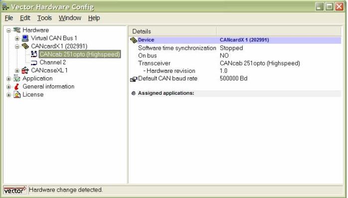
1. If you are a CANcardX user, the first thing to check is your Vector CANcardX driver version. The driver version can be found in the Vector Hardware Config screen by going to your PC’s Control Panel, then choosing either “CAN Hardware” or “Vector Hardware”.
Click on “CANcardX” and the driver version should appear in the right pane of the screen.
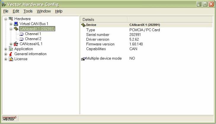
The driver version needs to be at 5.2.62 or above in order for the CDA to function properly. If your driver needs to be updated, then you’ll need to download the latest CANcardX driver (drvx52.zip) posted on the Chrysler Diagnostic Workbench under Tools> Software & Drivers and on the Supplier Diagnostic Workbench under SoftwareUpdates > PC Updates and update the driver. If you are not familiar with how to updatehardware on your PC, contact the Engineering Support help line or IT personnel
Make sure your transceiver cable (CANcab) is attached to CANcardX/XL and detectedby the Vector Hardware Config software prior to starting the CDA. You can checkwhether the cable is detected by going to the Vector Hardware Config screen (click Control Panel, then click either “CAN Hardware” or “Vector Hardware”) and clicking on your CANcardX/XL. The screenshot below shows what the screen will look like when the cable is detected.
Sometimes if logging is started with CANalyzer or CANoe on Channel X, and then the CDA is started and also connected to Channel X, the CDA may be blocked from using that channel. It is recommended that logging in CANalyzer or CANoe should not be started until after the CDA is launched.
Question 13:
Where do I get updated versions of the Chrysler Diagnostic Application?
Answer 13:
Updated versions of the application can be found in the Chrysler Diagnostic Workbench under Tools > CDA > Software & Drivers section and on the Supplier Diagnostic Workbench in the Software Updates section. There are separate files for the PC and StarSCAN versions of the application.
Question 14:
How do I find instructions on how to update my wiTECH VCI Pod or StarMOBILE software?
Answer 14:
See the CDA User Guide. On the Chrysler Diagnostic Workbench this can be found under Support select > Library > Library Filters>Applications> CDA User Guide. On the Supplier Diagnostic Workbench on the Home Page under the Latest News Section.
Question 15:
The ECU Diagnostic Package I am looking for is not available on the Diagnostic Workbench under My Workbench> ECU View. What is the process for having it released to the site?
Answer 15:
The ECU Release Engineer should contact the appropriate Core EE Vehicle Diagnostics (Art Merriweather’s team) team member to request that the ENG file for the ECU be released to the Chrysler Diagnostic Workbench (specifically My Workbench > ECU View / Vehicle View).
Question 16:
When do I need to use the ENG files found in on My Workbench under ECU View or Vehicle View?
Answer 16:
The ENG files are similar to the KWP01 files that were used with EDT2. The ENG files are required when attempting to communicate with and perform diagnostic functions on an ECU.The packages contain all data for the given variant of the ECU. You can search for .eng files by creating a filter under ECU View or for a specific Vehicle MY combination. Once you have the filters Diagnostic Data Results and have selected the specific files you need, you can then choose to download the entire ECU Diagnostic Package of just the .eng file by selecting the appropriate radio button before downloading.
Question 17:
When do I need the Gateway Configuration Package found in Tools > Software & Drivers?
Answer 17:
The Gateway Configuration Package is required in order to provide the Chrysler Diagnostic Application the ability to filter the list of ECUs shown to the user. Because the Central Gateway ECU contains LIDs/PIDs describing which ECUs are built on a given vehicle, the CDA can use this information to display only those ECUs. This is known as a CGW Filter. The GatewayConfiguration file is only necessary when using the CGW Filter, Vehicle Wide DTCs, and the Vehicle Scan features of the CDA.
Question 18:
What is Jira?
Answer 18:
Jira is an online system used to track issues, bugs, and new feature requests that emerge during a project. It provides a quick and effective way of notifying the development team of issues in order to get them resolved quickly. The Chrysler Diagnostic Application development team is using Jira as a portal for users to notify them of any issues or feature requests they encounter. For efficient resolution of issues, all correspondence regarding a specific Jira issues should be within the Jira project. The Jira project will notify the development team and the issue reporter via an automatic email when an update is entered In addition, Jira should also be used by ECU Release Engineers to request flash support for new ECUs.
Question 19:
I do not have login information for Jira. How can I get access?
Answer 19:
Chrysler Diagnostic Workbench users:
• You already logged into Jira when you logged into the Chrysler Diagnostic Workbench.
• To enter a Jira issue from the Chrysler Diagnostic Workbench select Support > Submit an Issue > Select one of the following Jira queues that pertains to your issue and the link will take you directly to the specific queue selected. You will not need to log in again.You can also submit an issue into the CDA or Diagnostic Workbench Jira queues fromTools > Support Links> Submit CDA Issue or Submit Diagnostic Workbench issue.
Supplier Diagnostic Workbench users:
• Your Supplier Diagnostic Workbench username and password will also log you into Jira.
• To enter a Jira issue on the Supplier Diagnostic Workbench, from the Home page select Jira > Login with your Diagnostic Workbench username and password. There is only one queue, CDA Support Queue (ETSQ).
Question 20:
On the Chrysler Diagnostic Workbench, which project should I use to create a new issue in Jira?
Answer 20:
Projects in Jira should be used as follows:
• Chrysler Diagnostic Application (CDA): Any bug, new feature, question, task or improvement issue related to the Chrysler Diagnostic application (CDA).
• Diagnostic Definition Tables (DDT)
• Diagnostic Workbench (DWB): Any bug, new feature, or task related to the Diagnostic Workbench site.
• DTC Application (DWB)
• Engineering ECU Flash Support (EEFS): Any bug, task, or question related to ECU flash support. In addition, ECU Flash Support Requests, Security Unlock
Implementation Requests (CVD and GSD only), and Noncompliant ECU Issues should be created here as well.
• EFD Builder (EFD): Any bug, new feature, or task related to the EFD Builder.
• Off Board Routines: Requests for support for specific Off Board routines are created here.
Question 21:
What are the differences between the PND and EFD file formats?
Answer 21:
The EFD (Extensible Flash Definition) file format was created to be a self-contained flash file which addressed many of the shortcomings of the PND file format. With PND, any special handling required in an ECU’s flash process, such as security unlocks, would require changes to the application code. EFD was designed to handle this through metadata in the file so that a generic flash application can be used and is not required to check for special requirements of the ECU during the flash process. The PND file format was originally created for J1850 flash,and later modified to support KWP2000 over CAN flash. Due to the modifications to the file format that would be required to support protocols such as UDS, the EFD file format was developed to be extendable and handle KWP2000, UDS, and future protocols. Other requirements of the flash process that are not provided for with PND but have been taken into account with EFD are non-sequential addresses in logical blocks, an ECU containing more than eight logical blocks, and multiple address handling.
Question 22:
Why don’t I see an ECU in the list of available ECUs in EFD Builder?
Answer 22:
You will not be able to build an EFD for an ECU until the CDA development team has received the metadata mentioned in the question above. Because this metadata is stored within the EFD file, it must be entered into the system before an EFD can be built. The ECU Release Engineer is responsible for requesting flash support for their ECU by creating a request in Jira. For more details on how to request flash support, see the ‘CDA New ECU Flash Support Process’ document located on the Chrysler Diagnostic Workbench site under Tools>Documentation & Training Aids section and on the Supplier Diagnostic Workbench site on the Home Page under Latest News.
Question 23:
Can EFD Builder and the CDA’s flash software support multiple address ranges or ‘holes’ in the memory map for each logical block?
Answer 23:
Yes, EFD Builder and the CDA’s flash software will support multiple address ranges for each logical block. When defining an ECU, EFD Builder supports multiple address range entries.
For example, an ECU may have a memory map of 0000-7FFF and C000-FFFF for logical block 1 and 8000-BFFF for logical block 2. When importing a s-record file having code for both logical blocks inside, EFD Builder will correctly parse the physical blocks into their correct logical blocks.
Question 24:
Can EFD Builder and the CDA’s flash software support overlapping logical blocks where the address ranges are the same for two logical blocks?
Answer 24:
Yes, as long as the code for each of the logical blocks are in separate s-record files. When importing an s-record file, if a particular physical block can belong to more than one logical block, EFD builder will ask which logical block the physical block belongs.
Question 25:
How many logical blocks can EFD Builder and the CDA’s flash software support?
Answer 25:
EFD Builder and the CDA’s flash software can support up to the theoretical maximum that the protocol allows. For the KWP2000 protocol, the maximum is 254 code logical blocks, 254 data logical blocks, and 254 boot logical blocks. For the UDS protocol, the maximum is 255 logical blocks.