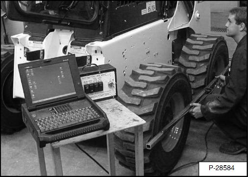
A calibration procedure must be followed when replacing a wheel position sensor, or Drive Plus Controller. Failure to calibrate after component replacement may result in poor performance.This instruction show you guide on how to perform wheel alignment calibration for Bobcat SSL A300 Skid Steer.
The tool needed to do the following procedure: Straight Edge 6 ft. Long
2023 Bobcat Service Analyzer 91.15 91.05 Diagnostic Free Download
WARNING
Put jackstands under the front axles and rear corners of the frame before running the engine for service.
Failure to use jackstands can allow the machine to fall or move and cause injury or death.
Place the loader on jackstands.(See the loader Service Manual for detailed instructions.)
Remove the four wheel/tire assemblies from the loader.
Remove the four steering cylinder pins at the hub.
Turn on the Remote Start Tool.
With an operator in the cab, seat bar down, start the loader and press THE PRESS TO OPERATE LOADER button.
Follow the Bobcat service analyzer for the procedure.
NOTE: If at any time during the procedure, the power to the loader is turned OFF before the wheels are aligned, the complete procedure must be repeated to insure correct alignment of the wheels.
NOTE: Code D7599 will be displayed by pressing info button four times.
Activate the calibration procedure and follow the steps in the service analyzer.
The wheels will then need to be check to make sure they are straight.
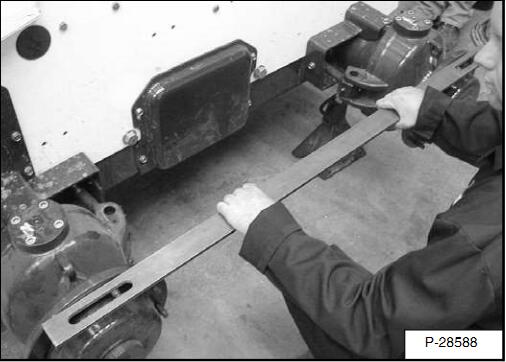
Place a straight edge along both hubs.
Use the straight edge as a reference to verify the two wheel hubs are in line with each other.
NOTE:The straight edge must contact the whole surface of each hub.
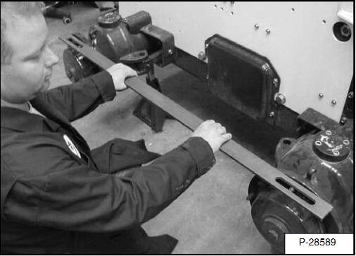
Move to the other side of the loader and place a straight edge along both hubs, and place the hubs in alignment.
After verifying the wheels are straight, again follow the service analyzer screen to complete the wheel alignment calibration.
The wheel sensors should display O on all wheels on the service analyzer.
The procedure is complete.
Install the steering pins in the hubs of the loader.
NOTE: When the steering cylinder pins are reinstalled in the hub, the wheels may be out of alignment. This will be corrected as soon as the loader is started, the PRESS TO OPERATE LOADER button is pushed, and the left joystick is moved.
Remove the Service Analyzer and Remote Start Tool.
With an operator in the cab, seat bar down, start the loader and press the PRESS TO OPERATE LOADER button.
Move the left joystick and the four wheels will move into alignment.
Shut the loader off.
Install the four wheel/tire assemblies from the loader.
Remove the loader from jackstands.
When wheels are not aligned, the wheels will not trackproperly when going forward /reverse and when in allwheel steer, the wheels will not track in a smooth arc when turning.
NOTE: This procedure must be performed with two people.
Turn the Remote Start Tool to the STOP position.
With an operator in the cab, seat bar down, start the loader and press THE PRESS TO OPERATE LOADER button.
Follow service analyzer screens to start wheel alignment.
NOTE: If at any time during the procedure, the power to the loader is turned OFF before the wheels are aligned, the complete procedure must be repeated to insure correct alignment of the wheels.
Audible beeps will sound to signal when the system is ready to align.
NOTE: Code D7599 will be displayed by pressing the info button four times.
The loader should now be in calibration mode.
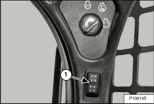
With the All-Wheel Steer/Skid-Steer selector switch
(Item 1)[ Figure 3] in the Skid-Steer Mode, the left front wheel and left rear wheel can be aligned.
NOTE: The All-Wheel Steer /Skid-Steer selector switch and the position of the let joystick determine the side of the loader and the wheel that is to be aligned.
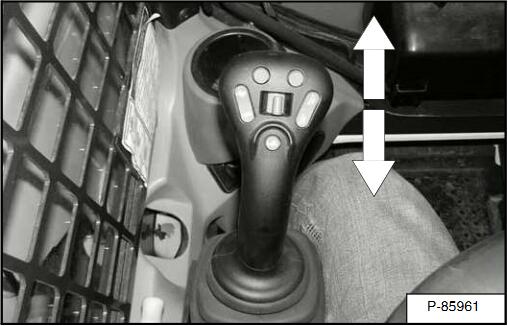
Move the left joystick forward and backward to align the left rear wheel.
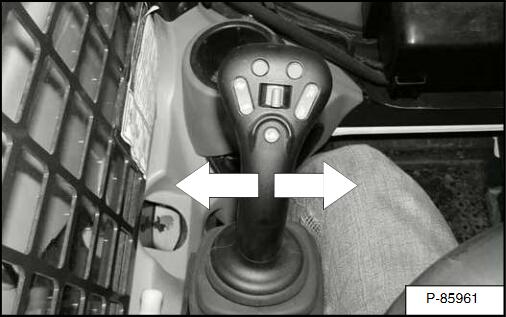
Move the left joystick from side to side to align the left front wheel.
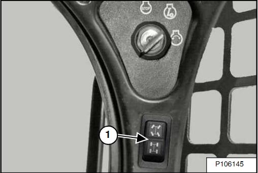
Press the AWS switch(Item 1) into the AWS Mode, the right front wheel and right rear wheel can be aligned.
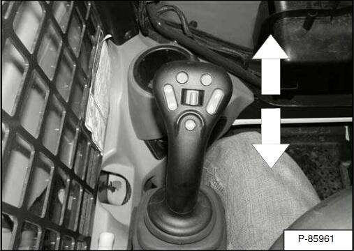
Move the left joystick forward and backward to align the right rear wheel.
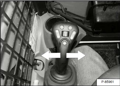
Move the left joystick from side to side to align the right front wheel.
NOTE: Allow the joystick to go to neutral position before clicking [ OK] on the service analyzer screen.
Click OK on the service analyzer screen to complete the Wheel Alignment(Field Adjustment).
The wheel sensors should display 0 on all wheels on the service analyzer screen.
Use a straight edge along both tires to check the wheel alignment.
If the wheels are not aligned, check the sensors, linkages or steering cylinders.
If one or both wheels need to be aligned, repeat the complete procedure to insure correct alignment.
The procedure is completed for both sides of the loader.
Shut the loader off.
Wheel alignment is complete.
More Bobcat excavator repair,please refer to:Bobcat excavator repair.