This article involves:verifying if a low transmission line pressure condition is/was present, replacing the Transmission Control Module (TCM) if necessary, and inspecting for possible transmission clutch disc wear.
MODELS:
2004 (WJ/WG) Grand Cherokee
2004 – 2005 (KJ) Cherokee (International Market)
2005 (KJ) Liberty
NOTE: This bulletin applies to a Grand Cherokee, Liberty, or Cherokee equipped with a 545RFE automatic transmission (sales code DGQ) and built on or between April 07, 2004 (MDH 0407XX) and February 27, 2005 (MDH 0227XX).
And for more Jeep repair case,check here:Jeep Repair Case
SYMPTOM/CONDITION:
The customer may notice that the Malfunction Indicator Lamp (MIL) has illuminated and that the transmission may be in “Limp-In” mode. Further investigation by the technician may reveal that the MIL illumination may be due to transmission Diagnostic Trouble Codes (DTC’s) relating to either a “Low Line Pressure” fault and/or to a “Gear Ratio Error” fault.
This condition may be intermittent. If a DTC has occurred then “DTC Event Data” relating to the respective DTC will have been captured and logged in the TCM and may be obtained using the DRB III® scan tool.
DTC’s That This Condition May Cause:
P0868 – Line Pressure Low.
P0731 – Gear Ratio Error In 1st.
P0732 – Gear Ratio Error In 2nd.
P0733 – Gear Ratio Error In 3rd.
P0734 – Gear Ratio Error In 4th.
P0735 – Gear Ratio Error In 5th.
P0736 – Gear Ratio Error In Reverse.
P1736 – Gear Ratio Error In 2 prime.
The cause of the above condition may be due to an internal electronic circuit failure within the TCM. The Grand Cherokee vehicles equipped with a 545RFE transmission will have either a 4.7L or 4.7L H.O. engine. Liberty and Cherokee vehicles equipped with a 545RFE transmission will have a 2.8L diesel engine. This bulletin DOES NOT apply to vehicles equipped with any other type of automatic transmission.
DIAGNOSIS:
The build date of the TCM must be inspected for a specific build time (range). The suspect build range is from April 04, 2004 (Julian date of 0984 where: “098“ = day of year, and “4” = 2004) to February 09, 2005 (Julian date of 0405 where: “040” = day of year, and “5” = 2005). Any TCM built between Julian dates 0984 to 0405 may be suspect if one or more of the above DTC’s have occurred.
The above date codes (Julian dates) are displayed on the bar code label that is affixed to the outside of the TCM. The bar code will be an eleven (11) digit number. Read the third (3rd) through the sixth (6th) digit to determine the date of build of the TCM. An example of a bar code number is “TH098412345”. “TH” represents the type controller and vendor.“0984” represents the date code that the TCM was built using the Julian date coding method. “12345” represents the unique serial number for the sequence of build of the controller for the specific Julian date (day).
1.Verify that the build date code on the TCM falls within the suspect build date range of 0984 to 0405. If the vehicle TCM date code falls within the suspect date range proceed to the next step. If not, then this bulletin does not apply and further diagnosis isrequired.
2.If DTC P0868 is present, then perform the Repair Procedure. If not, proceed to the next step.
3.If the DTC is one of the above “Gear Ratio Error” faults listed above, then proceed to the next step. If not, then this bulletin does not apply and further diagnosis is required.
4.Using the DRB III® scan tool, check the “DTC Event Data”. Is the “Line Pressure” reading displayed in the “DTC Event Data” within 103 Kpa (15 psi) of the “Desired Line Pressure” reading? If yes, then this bulletin does not apply and further diagnosis is required. If the “Line Pressure” reading is 103 Kpa (15 psi) or more below the “Desired Line Pressure”, then perform the Repair Procedure.
PARTS REQUIRED:
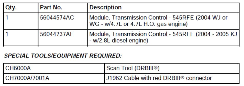
NOTE: An updated J1962 cable has been released. This cable has a red colored connector at the DRBIII® connection.
REPAIR PROCEDURE:
1.Disconnect and isolate the negative battery cable from the battery.
2.Replace the Transmission Control Module (TCM).
3.Connect the negative battery cable to the battery, set the clock to the correct time, and clear any TCM DTC’s which may be present.
4.Using the DRBIII®, compare the “Actual Line Pressure “ reading to the “Desired Line Pressure” value (goal) with the vehicle in Park and the engine running at 1,500 RPM.
5.If the “Actual Line Pressure” reading is less than the “Desired Line Pressure” value by 103 Kpa (15 psi) or more, then further diagnosis and repair of the transmission will be required. Refer to NOTE below.
6.The transmission line pressure is considered good/normal if the “Actual Line Pressure” reading is within +/- 34 Kpa (+/- 5 psi) of the “Desired Line Pressure” value.Momentary small fluctuates in “Actual Line Pressure” greater than +/- 34 Kpa (+/- 5 psi) may occur. If the “Actual Line Pressure” reading is within +/- 34 Kpa (+/- 5 psi) of
the “Desired Line Pressure” value, proceed to the next step.
7.Using the DRBIII®, perform a 1st Gear Clutch Test and a Reverse Gear Clutch Test. If either test fails (input speed does not remain at zero), then further diagnosis and repair of the transmission will be required. Refer to NOTE below.
8.If the 1st Gear Clutch Test and the Reverse Gear Clutch Test pass, then proceed to the next step.
NOTE: If the “Actual Line Pressure” is below specification (less than 103 Kpa / 15 psi) of the “Desired Line Pressure, or if either the 1st Gear Clutch or the Reverse Gear Clutch Tests fail, then repair to the transmission may be required. Remove the transmission, inspect the clutches and repair as necessary. Often corrective action may only involve repair to a specific set of clutch discs and separator plates (clutch pack). Possible repair to the
transmission is not addressed by this Service Bulletin.
NOTE: If the transmission requires disassembly for repair to mechanical components, verify that the pump gears are intact and that the main regulator valve (located in the pump valve body) moves freely in its bore.
9.Using the DRBIII®, perform the transmission Quick Learn Procedure.
10.Perform the transmission diagnostic Verification Procedure. Refer to TechCONNECT for detailed instructions, Diagnostic Tab, 7.0 Diagnostic Information and Procedures,7.3 Verification Tests.
NOTE: If any of the above listed DTC’s reoccur after performing the Quick Learn and Verification Procedures, then further transmission diagnosis and repair will be required.
POLICY:
Reimbursable within the provisions of the warranty.